
Plastic bag dispensing unit

a dispensing unit and plastic bag technology, applied in the direction of thin material handling, article delivery, shop counters, etc., can solve the problems of unusable bags, waste of user time, and inability to completely prevent the spinning off of multiple bags, so as to prevent waste of time, prevent multiple feeds, and facilitate docking and positioning

Inactive Publication Date: 2007-09-25
TRINKO GRP LLC
View PDF18 Cites 11 Cited by
  • Summary
  • Abstract
  • Description
  • Claims
  • Application Information

AI Technical Summary

Benefits of technology

The system ensures accurate, single-bag dispensing, maintaining hygiene and reducing waste by balancing electrostatic bonds against drag forces, allowing easy access to clean plastic bags without manual handling or tearing, and is economical and durable in design.

Problems solved by technology

Plastic bags are bulky and must be folded or rolled for packaging and transportation.
Yet, even the best attempts to redesign the dispensing rack have not totally prevented multiple bags from spinning off from the roll at the first tug by a user.
Even if the next bag is prevented from dispensing, the bags may tear along the body of the bag and not along the perforations, thereby rendering the bag unusable.
Thus, the user is then left with the frustrating task of either rolling the bags back up onto the roll and trying again or tearing the bags apart by hand and leaving the others to waste.
In addition to creating waste and the user becoming frustrated, malfunctions more often than not result in the user physically handling subsequent bags.
More importantly, if the user handles the open end of the bag the bag may no longer be hygienically safe.
Furthermore, dispensing the plastic bags starting from the center of the roll may create additional concerns and possible malfunctions.
For example, the role could become entirely unusable if the perforations fail before the next bag is pulled from the center of the role.
Still, attempts to grab the bag now stuck in the center of the roll could result in increased user frustration and additional waste.
Thus, the bags and bag openings are exposed to physical handling and run the risk of becoming contaminated.
Because the user must rotate the entire roll to dispense one bag from the roll this configuration is highly susceptible to malfunctions.
In particular, if the static binding is less than the rotational resistance of the roll the dispensing bag will prematurely detach from the next bag.
Thus, the user has to often handle the bags extensively in search for the lost end of the bag within the container.

Method used


Image

  • Plastic bag dispensing unit
  • Plastic bag dispensing unit
  • Plastic bag dispensing unit

Examples


Embodiment Construction

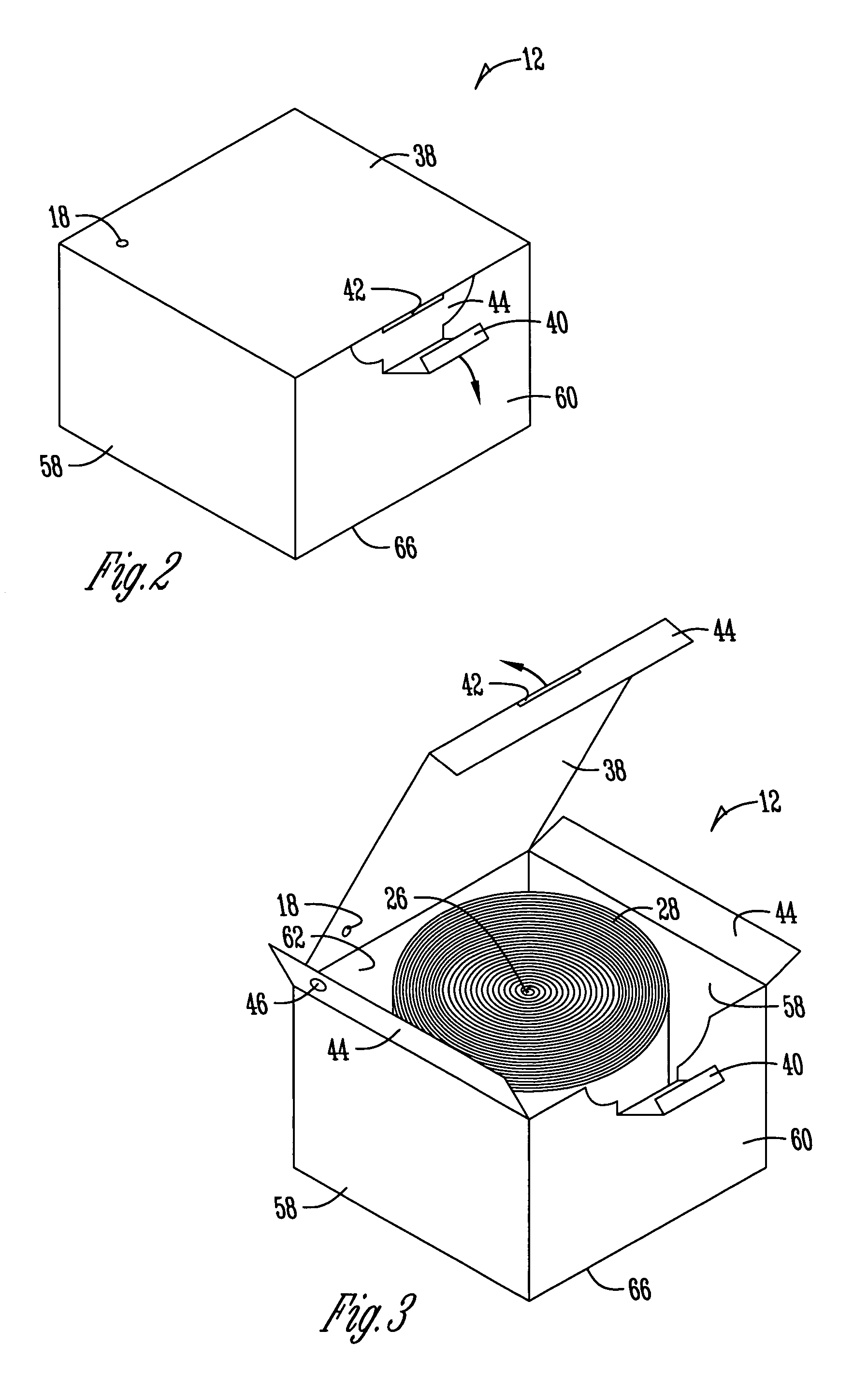
[0043]Turning now to the drawings in which similar reference characters denote similar elements through the several views, illustrated in FIGS. 1-7 is the combination of various views and in-use configurations of the plastic bag dispensing unit. The plastic bag dispensing unit being described with particularity herein.

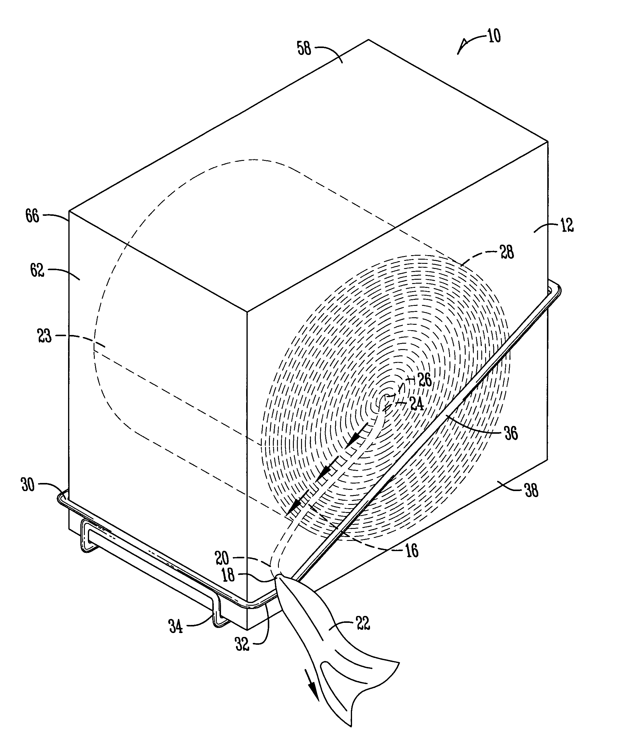
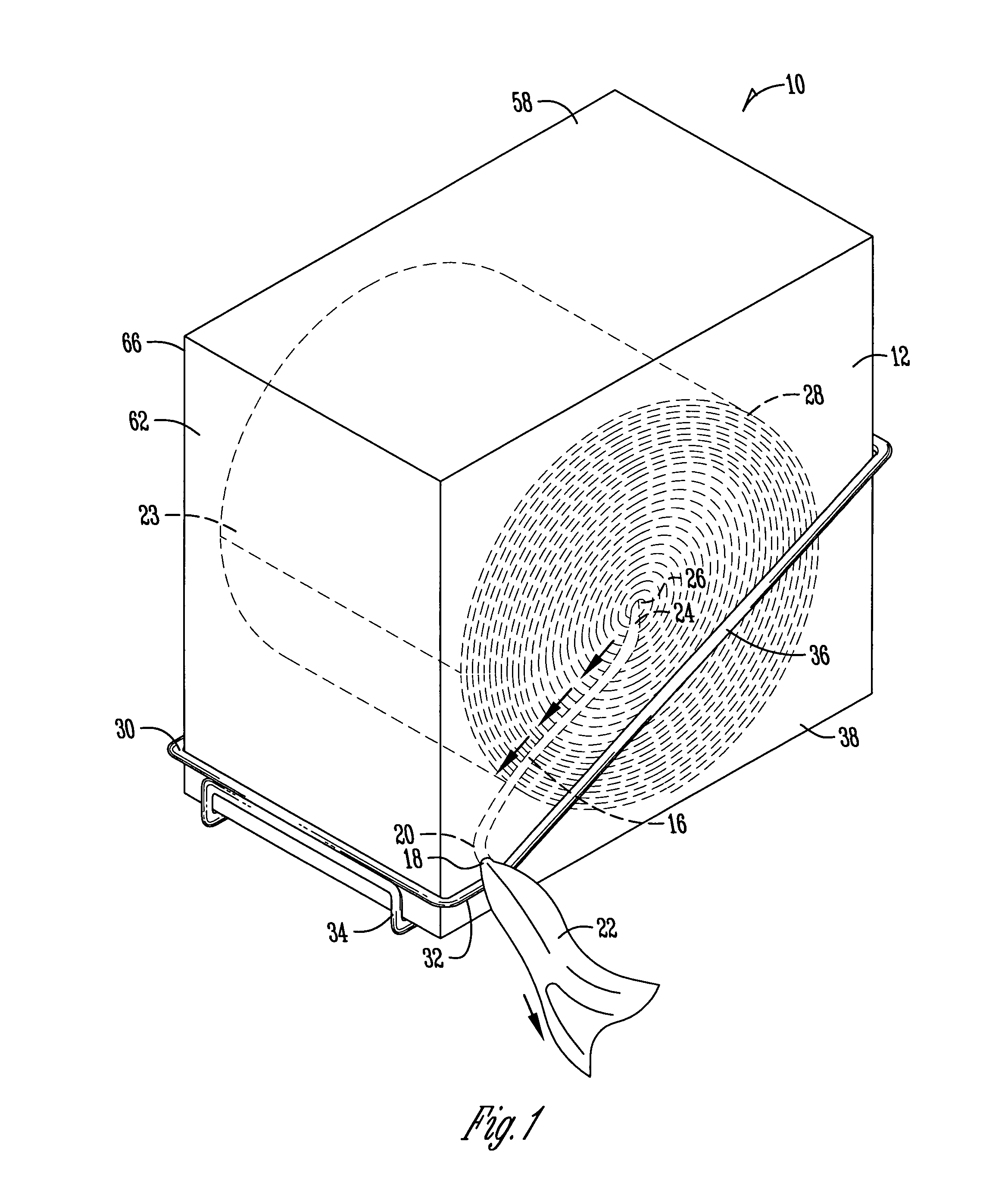
[0044]The plastic bag dispensing unit is referred to generally as 10. As seen in FIG. 1, the plastic bag dispensing unit has a axial center dispensing plastic bag roll 28 housed in a dispensing carton 12 being docked in a dispensing rack 14.

[0045]The rolled plastic bags 28 have a dispensing end 22 and a non-dispensing end 23. The dispensing end 22 and non-dispensing end 23 form the opposite ends of the rolled plastic bags 28. The dispensing end 22 is pulled from the axial center 26 bent along the axial center angle 24, follows the feed pathway 16, bends along the dispensing aperture angle 20 and exits the dispensing carton 12 through the lid dispensing aperture 18. The...


PUM

PropertyMeasurementUnit
degree angleaaaaaaaaaa
angleaaaaaaaaaa
electrostatic forcesaaaaaaaaaa

Abstract

A plastic bag roll, dispensing container and service rack combination allows easy docking and positioning of a dispensing carton into a service rack mountable for varied configurations. The dispensing container is specifically crafted to house a roll of plastic bags. A bag is drawn from the center of the role, pulled along the feed pathway and threaded through the dispensing apertures. The electrostatic binding of the individual bags is balanced against the drag generated along the feed pathway and dispensing apertures to insure smooth and accurate disbursement of a single, hygienically safe plastic bag.

Description

CROSS-REFERENCE TO RELATED APPLICATIONS[0001]This application is a continuation-in-part of U.S. patent application Ser. No. 10 / 357,674 filed on Feb. 4, 2003, now U.S. Pat. No. 7,066,422 which is a nonprovisional U.S. application, herein incorporated by reference in its entirety.FIELD OF THE INVENTION[0002]The present invention relates generally to a plastic bag dispenser and more specifically to a plastic bag dispenser using a continuous roll of overlapping plastic bags enclosed in a dispensing carton promoting hygienics and supported by a service rack to insure flawless disbursement of a single bag by preventing jams, feeding malfunctions and multiple feeds.BACKGROUND OF THE INVENTION[0003]Plastic bags are bulky and must be folded or rolled for packaging and transportation. For example, a typical 24″ wide by 24″ high plastic bag has a 7 to 10 gallon capacity when filled. Therefore, plastic bags are typically folded to reduce the width in half or a quarter of the original size, fold...

Claims


Application Information

Patent Timeline
Patent Type & Authority Patents(United States)
IPC IPC(8): B65H75/28B65H18/28
CPCB65H18/28B65H20/26B65H29/006B65H2301/5132B65H2701/191A47F2009/044
Inventor SLOCUM, TRACY LEETRINKO, DOMINIC
Owner TRINKO GRP LLC
Learn More