A blind system and method of retrofitting a blind system

a blind system and retrofitting technology, applied in the field of blind systems, can solve the problems of installation risk, installation difficulty, installation difficulty, etc., and achieve the effect of improving performan

Pending Publication Date: 2022-04-21
ROLLEASE ACMEDA
View PDF5 Cites 0 Cited by
  • Summary
  • Abstract
  • Description
  • Claims
  • Application Information

AI Technical Summary

Benefits of technology

[0010]In some forms, an improved motor is provided which comprises a second recess that extends radially about the longitudinal axis, the second recess being configured to receive an antenna that is able to be wrapped around the motor such that it is positioned in the second recess of the motor. This arrangement allows for the antenna to be housed (completely or partially) within the second recess and manipulated by a user to enhance performance while retaining a clean look and not interfering with the fabric of the window covering.
[0011]In some improved forms, a button is disposed in the second recess, wherein the button is configured to turn the motor on and off upon depression of the button by a user. This arrangement reduces the prospect of the button being accidentally pressed and may also means that no device (e.g. a specific tool) is required to press the button.

Problems solved by technology

This is time consuming for the installer and, depending on the position of the blind, may not always be possible (e.g. where the difference in width is small, it may not be possible to relocate the brackets due to the location of pre-existing mounting apertures in a wall).
This may result in an insufficient connection between the brackets and the blind (e.g. where the connection is threaded, the full thread may not be used to secure the blind to one or both supporting brackets), which may lead to a dangerous installation (e.g. risk of the blind falling).
This arrangement reduces the prospect of the button being accidentally pressed and may also means that no device (e.g. a specific tool) is required to press the button.

Method used


Image

  • A blind system and method of retrofitting a blind system
  • A blind system and method of retrofitting a blind system
  • A blind system and method of retrofitting a blind system

Examples


Embodiment Construction

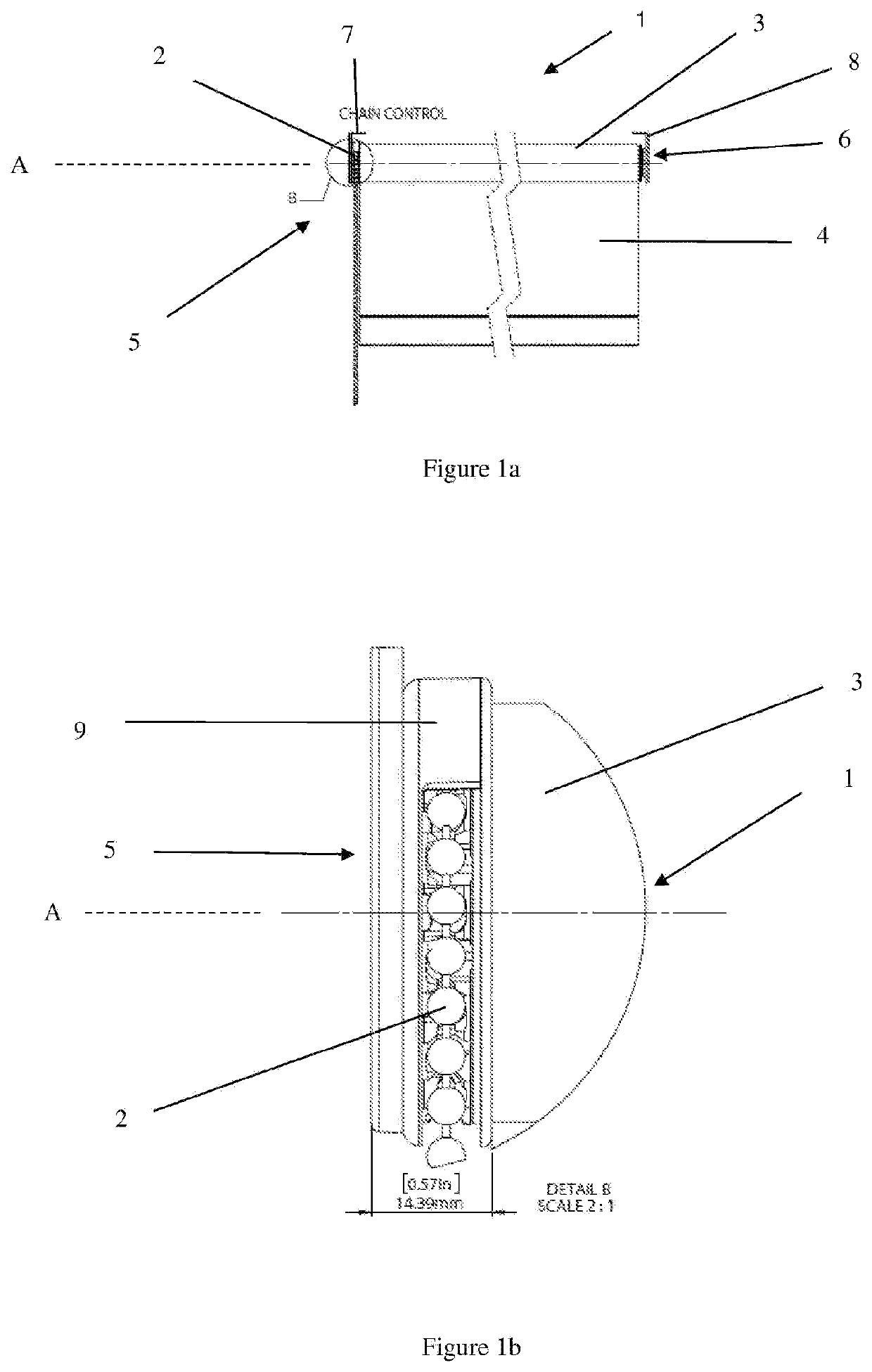
[0034]FIGS. 1a-b show a side view of prior art blind system 1. The prior art blind system 1 includes a chain 2 that is coupled to a rotatable chain drive (not shown) for manual operation of the blind. The blind system 1 includes an elongate rod 3 for supporting a blind, in the form of a window covering 4. The rod 3 extends along a longitudinal axis A of the blind system 1 between first 5 and second 6 opposing ends of the rod 3. The first 5 and second 6 ends of the rod 3 are configured to connect the blind system 1 to first 7 and second 8 brackets respectively to support the blind system 1 on a surface (e.g. on a wall adjacent a window).

[0035]The chain drive of the blind system 1 is connected to a spindle (not shown) that extends along the longitudinal axis A. The spindle is configured to rotate the rod 3 about the longitudinal axis A upon manual operation of the chain 2 (e.g. by a user pulling on a length of chain to rotate the chain drive) to extend and retract the window covering ...


PUM

PropertyMeasurementUnit
widthaaaaaaaaaa
resilientaaaaaaaaaa
poweraaaaaaaaaa

Abstract

Disclosed herein is a blind system. The system includes an elongate rod for supporting a length of fabric. The system includes a motor that is connected to a spindle that is configured to rotate the rod about the longitudinal axis to extend and retract the blind in use. The motor may be disposed at a first end of the rod and may have a recess formed therein that is configured to receive a projecting portion of the support.

Description

TECHNICAL FIELD[0001]The disclosure relates to a blind system. The blind system has an elongate rod and a motor configured to rotate the rod to extend and retract a blind. A method of retrofitting a blind system is also disclosed. The method comprises replacing a chain winder with a motor and a support that enables the retrofitted system to be mounted to existing brackets.BACKGROUND ART[0002]A blind system may be rotatable to, for example, extend and retract a window covering such as a window blind. Such assemblies may include a manually driven chain drive that rotates a drive spindle. The drive spindle is configured to cause the blind system to rotate to retract and extend the blind.[0003]Blind systems may be retrofitted with a winder motor. Retrofitting a blind system with a motor may include replacing the chain drive with a winder motor. Winder motors may be connected to the existing drive spindle. The width of a winder motor may not be the same as the width of the replaced chain...

Claims


Application Information

Patent Timeline
Patent Type & Authority Applications(United States)
IPC IPC(8): E06B9/72E06B9/50H01M10/46H01M10/48
CPCE06B9/72E06B9/50E06B2009/689H01M10/488H01M10/46E06B9/42E06B9/70H02J7/0048H02J7/0063Y02E60/10
Inventor BOTHA, STEFAN
Owner ROLLEASE ACMEDA
Why Eureka
Try Eureka