Balloon catheter having a multilayered shaft with variable flexibility

Inactive Publication Date: 2007-09-25
ABBOTT CARDIOVASCULAR
View PDF22 Cites 27 Cited by
  • Summary
  • Abstract
  • Description
  • Claims
  • Application Information

AI Technical Summary

Benefits of technology

[0014]The catheter of the invention has excellent pushability, kink resistance, flexibility, and low profile, for improved ability to be advanced through a patient's tortuous anatomy and position the balloon or oth

Problems solved by technology

Substantial, uncontrolled expansion of the balloon against the vessel wall can cause trauma to the vessel wall.
However, this progression has also increased the difficulty in forming smooth transitions bet

Method used


Image

  • Balloon catheter having a multilayered shaft with variable flexibility
  • Balloon catheter having a multilayered shaft with variable flexibility
  • Balloon catheter having a multilayered shaft with variable flexibility

Examples


Embodiment Construction

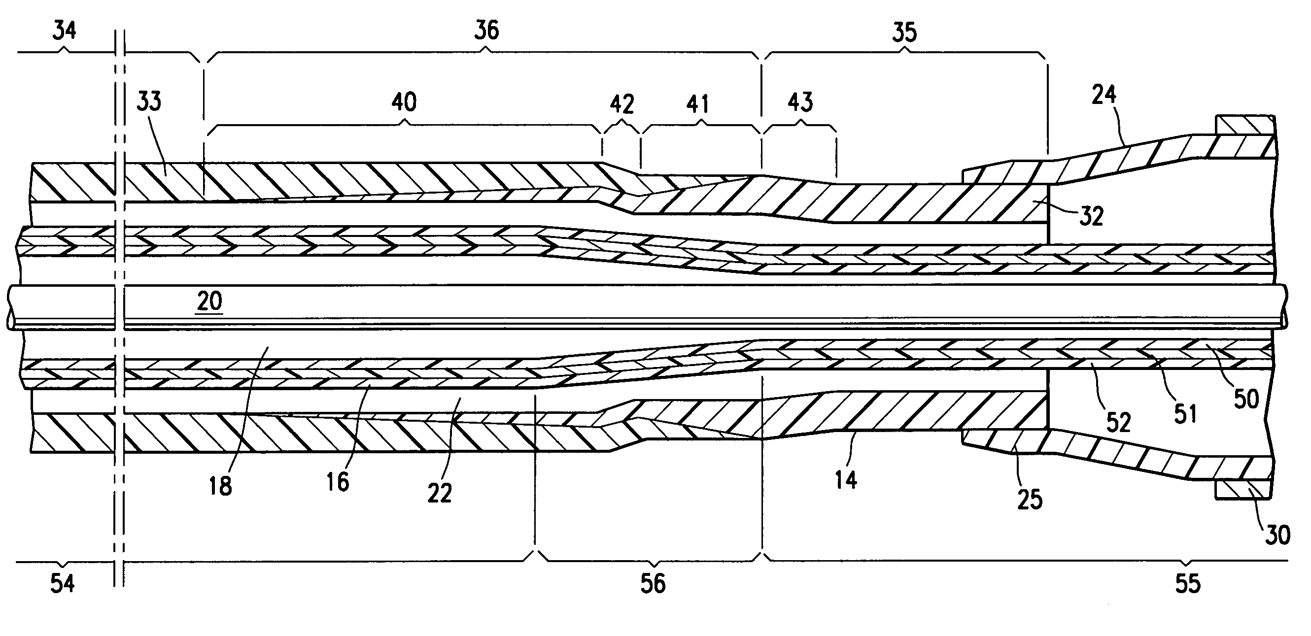
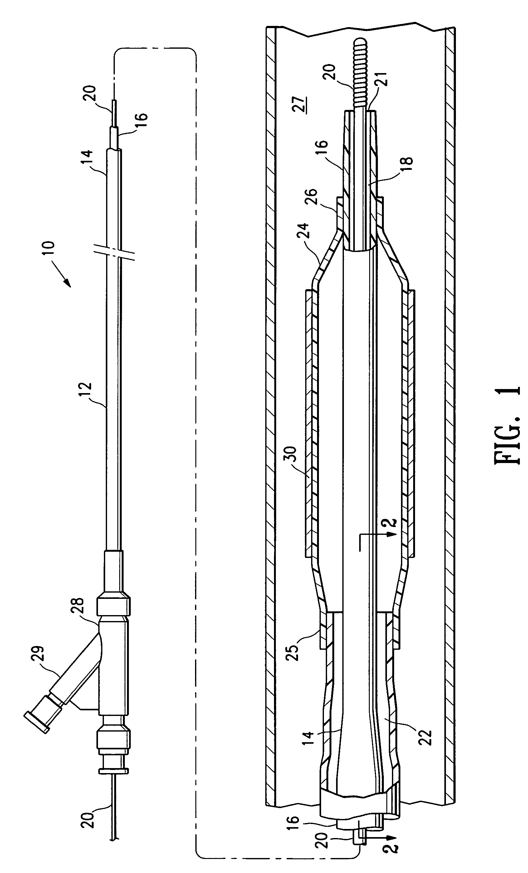
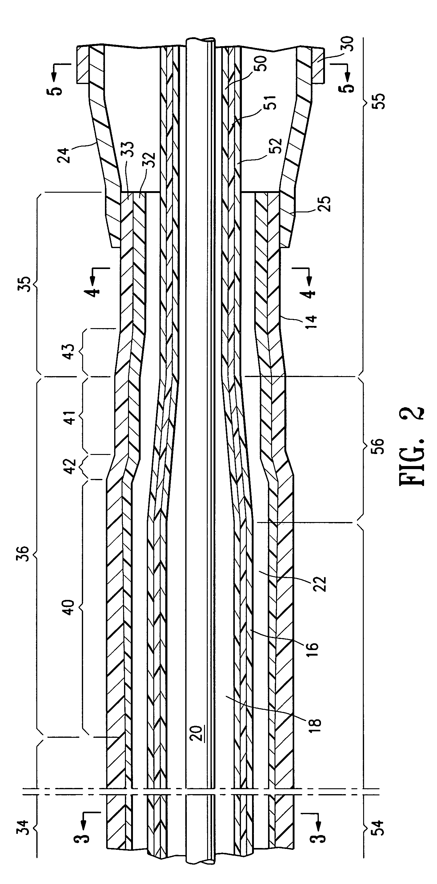
[0019]FIG. 1 illustrates an over-the-wire type stent delivery balloon catheter 10 embodying features of the invention. Catheter 10 generally comprises an elongated catheter shaft 12 having an outer tubular member 14, and an inner tubular member 16 extending in the outer tubular member 14 from the proximal to the distal end of the catheter shaft. Inner tubular member 16 defines a guidewire lumen 18 configured to slidingly receive a guidewire 20, and the outer tubular member 14 defines an inflation lumen 22, as best shown in FIG. 3 illustrating a transverse cross section of the distal end of the catheter shown in FIG. 1, taken along line 3-3. In the embodiment of FIG. 1, the inflation lumen 22 has an annular shape as a result of the coaxial relationship between outer tubular member 14 and inner tubular member 16. Guidewire 20 extends out the distal end of the catheter through a distal guidewire port 21. An inflatable balloon 24 disposed on a distal section of catheter shaft 12 has a p...


PUM

PropertyMeasurementUnit
Fractionaaaaaaaaaa
Fractionaaaaaaaaaa
Fractionaaaaaaaaaa

Abstract

A balloon catheter having a multilayered shaft with variable flexibility along the length of the shaft. In a presently preferred embodiment, the multilayered shaft has a multilayered outer tubular member and an inner tubular member, both the inner and outer tubular members having sections along which the flexibility and/or diameter of the tubular members decrease. These diameter and flexibility transition sections along the outer tubular member are preferably aligned with transitions along the inner tubular member, to provide improved catheter performance.

Description

BACKGROUND OF THE INVENTION[0001]This invention generally relates to medical devices, and particularly to intracorporeal devices for therapeutic or diagnostic uses, such as balloon catheters.[0002]In percutaneous transluminal coronary angioplasty (PTCA) procedures, a guiding catheter is advanced until the distal tip of the guiding catheter is seated in the ostium of a desired coronary artery. A guidewire, positioned within an inner lumen of a dilatation catheter, is first advanced out of the distal end of the guiding catheter into the patient's coronary artery until the distal end of the guidewire crosses a lesion to be dilated. Then the dilatation catheter having an inflatable balloon on the distal portion thereof is advanced into the patient's coronary anatomy, over the previously introduced guidewire, until the balloon of the dilatation catheter is properly positioned across the lesion. Once properly positioned, the dilatation balloon is inflated with fluid one or more times to a...

Claims


Application Information

Patent Timeline
IPC IPC(8): A61M29/00
CPCA61M25/0045A61M25/0054A61M25/104
Inventor DUCHAMP, JACKY G.SANDERS, KEITH G.
Owner ABBOTT CARDIOVASCULAR
Why Eureka
Try Eureka