Non-planar microfabricated gas chromatography column

a gas chromatography column and microfabricated technology, applied in the field of microanalytical systems, can solve the problems of narrow-bore capillary column low sample capacity and working range, poor detection limits in packed columns, and band broadening, so as to achieve the effect of minimizing the broadening

a gas chromatography column and microfabricated technology, applied in the field of microanalytical systems, can solve the problems of narrow-bore capillary column low sample capacity and working range, poor detection limits in packed columns, and band broadening, so as to achieve the effect of minimizing the broadening

US7273517B1Active Publication Date: 2007-09-25NAT TECH & ENG SOLUTIONS OF SANDIA LLC

Image

  • Non-planar microfabricated gas chromatography column
  • Non-planar microfabricated gas chromatography column
  • Non-planar microfabricated gas chromatography column

Examples


Embodiment Construction

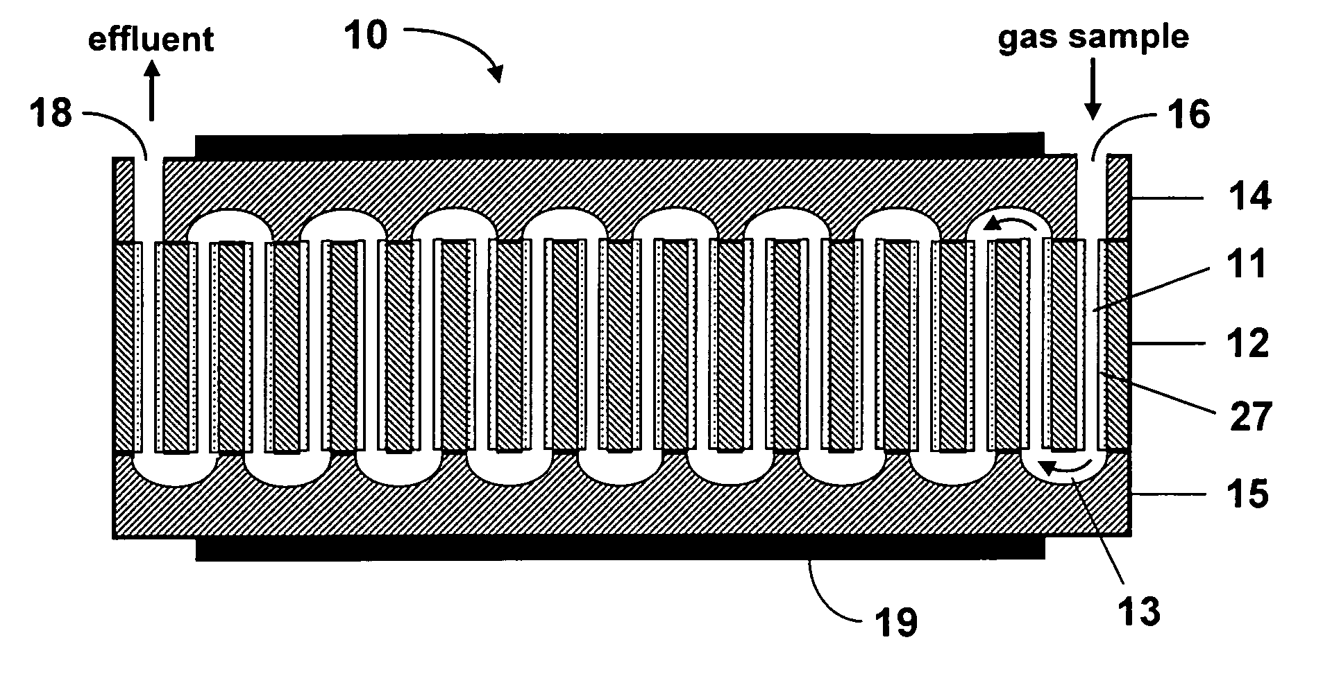
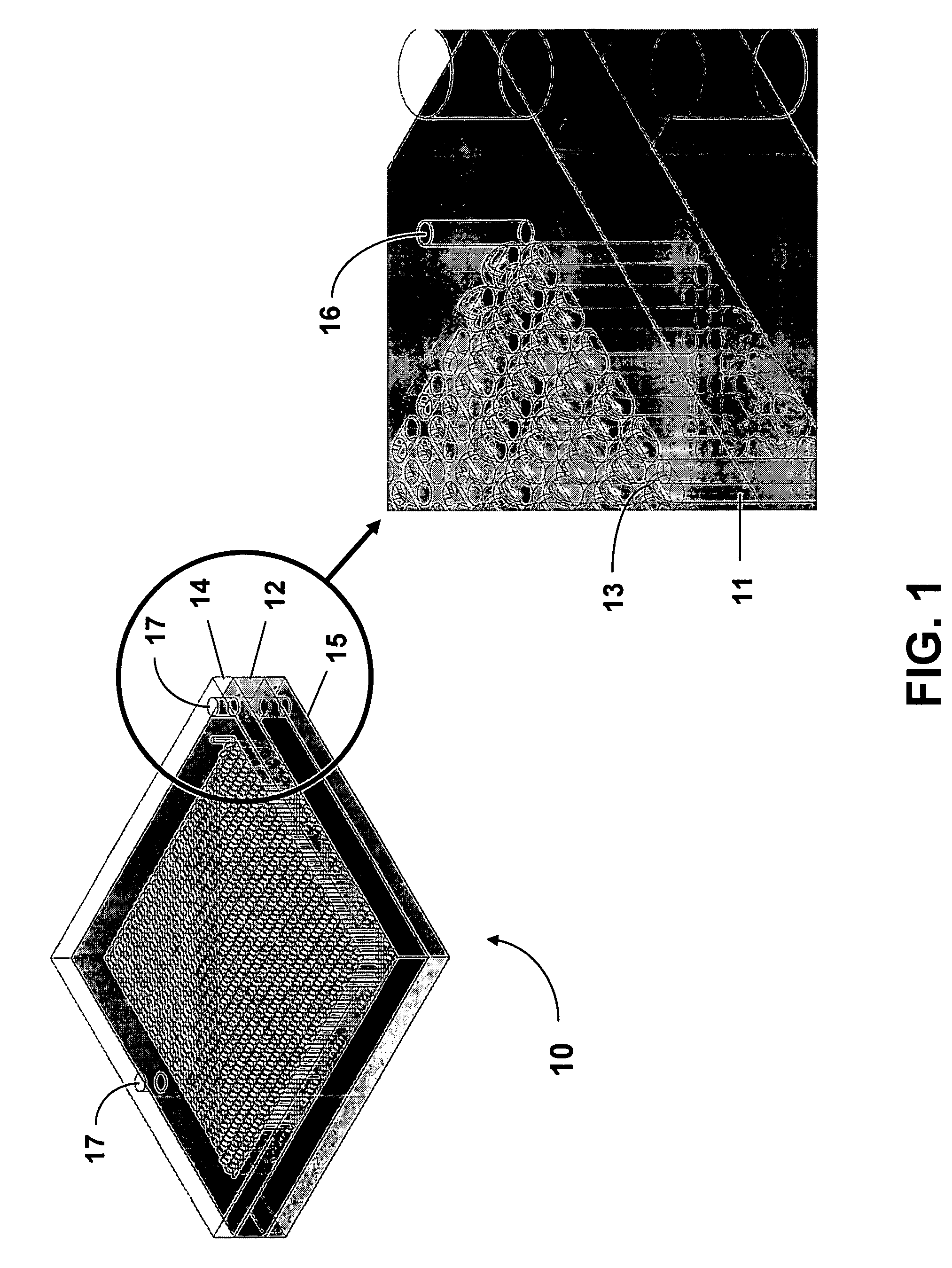
[0016]In FIG. 1 is shown a schematic illustration of an exemplary non-planar microfabricated GC column 10 of the present invention. The column 10 comprises a parallel array of holes 11 etched through a planar substrate 12. The sidewalls of the holes 11 can be coated with a stationary phase, or the holes can be filled with a porous packing material. The ends of adjacent holes 11 can be interconnected in a serial arrangement by rectangular or semicircular vias 13 (e.g., 180° elbows or half-annuli) formed in a top lid 14 and a bottom lid 15. As shown, the interconnected holes can form a continuous serpentine flow channel, much like a shell and tube heat exchanger. An inlet port 16, for injection of a sample gas mixture, and an outlet port (not shown), for elution of the separated analytes, can be formed through the lids 14 and 15. The substrate 12 and top and bottom lids 14 and 15 can be aligned by means of alignment pins 17 and bonded together to form a leak-tight seal.
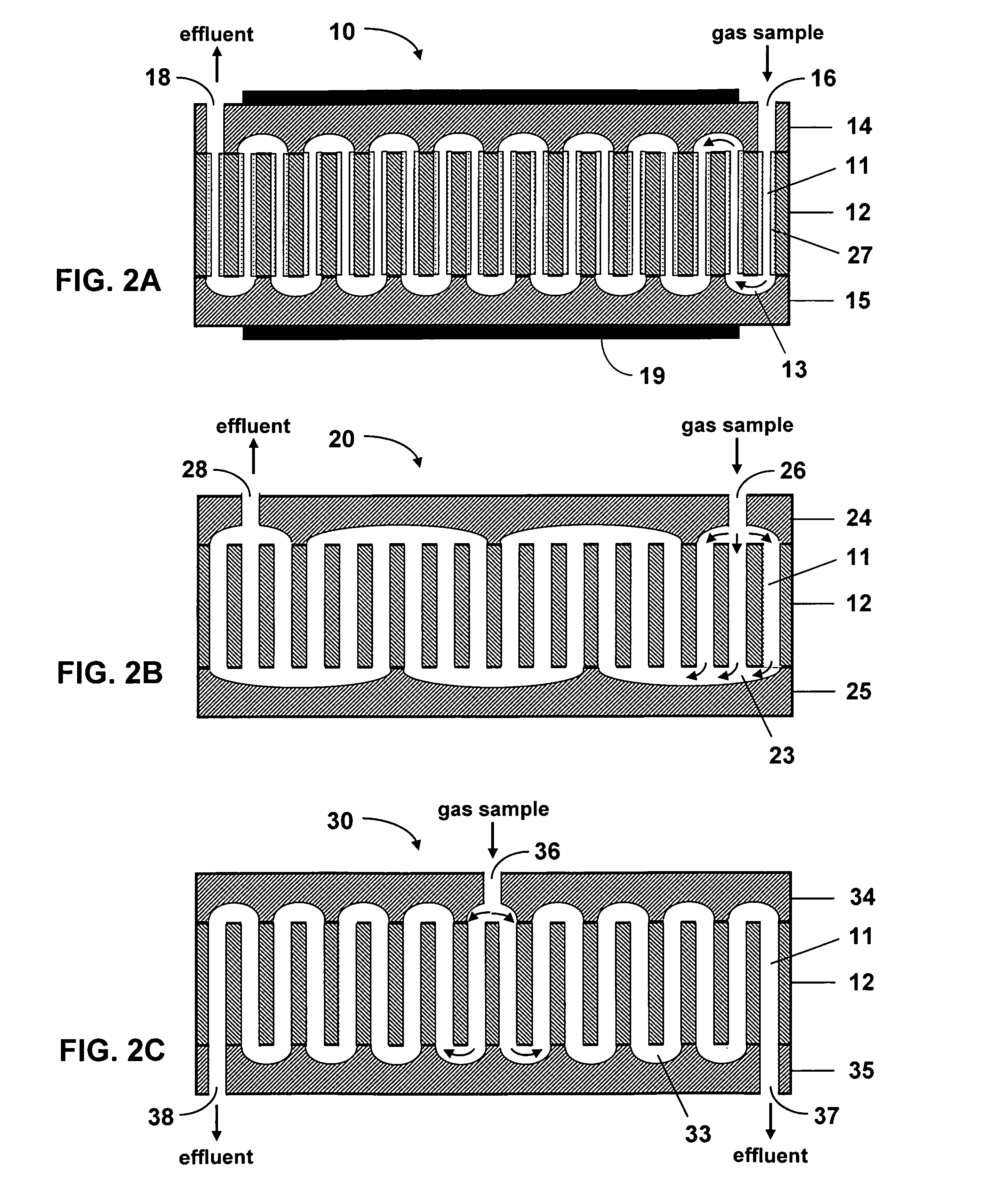
[0017]FIG. 2A s...


PUM


Abstract

A non-planar microfabricated gas chromatography column comprises a planar substrate having a plurality of through holes, a top lid and a bottom lid bonded to opposite surfaces of the planar substrate, and inlet and outlet ports for injection of a sample gas and elution of separated analytes. A plurality of such planar substrates can be aligned and stacked to provide a longer column length having a small footprint. Furthermore, two or more separate channels can enable multi-channel or multi-dimensional gas chromatography. The through holes preferably have a circular cross section and can be coated with a stationary phase material or packed with a porous packing material. Importantly, uniform stationary phase coatings can be obtained and band broadening can be minimized with the circular channels. A heating or cooling element can be disposed on at least one of the lids to enable temperature programming of the column.

Description

STATEMENT OF GOVERNMENT INTEREST[0001]This invention was made with Government support under contract no. DE-AC04-94AL85000 awarded by the U.S. Department of Energy to Sandia Corporation. The Government has certain rights in the invention.FIELD OF THE INVENTION[0002]The present invention relates to microanalytical systems and, more particularly, to a non-planar microfabricated gas chromatography column that can be used to separate chemical analytes in a gas sample mixture.BACKGROUND OF THE INVENTION[0003]Gas chromatography (GC) relies upon the chemical equilibria of analytes between a mobile phase and a stationary phase in a GC column to bring about a temporal separation of the analytes in a gas mixture into a series of elution bands. Most current methods of gas chromatography rely on an open capillary tube with a stationary phase coating the inner wall of the tube to generate chemical separations. In addition, GC columns that are packed with a support that can be coated with a stati...

Claims


Application Information

Patent Timeline
25 Sep 2007
Publication
US7273517B1
IPC
B01D53/02
CPC
G01N30/6095; G01N2030/025
Inventors
LEWIS, PATRICK R.; WHEELER, DAVID R.