Induction hob with monobloc housing components

a technology of monobloc and housing components, which is applied in the direction of hot plate heating arrangements, electric/magnetic/electromagnetic heating, milk preservation, etc., can solve the problems of requiring a large amount of complex procedures to prolong assembly work time, and achieve the effect of increasing functionality and facilitating assembly

Inactive Publication Date: 2007-09-25
BOSCH SIEMENS HAUSGERATE GMBH
View PDF5 Cites 29 Cited by
  • Summary
  • Abstract
  • Description
  • Claims
  • Application Information

AI Technical Summary

Benefits of technology

[0030]A further advantage of the invention is the ease of assembly when shifting the induction mechanism carrier between the assembly position and the operating position or during assembly or disassembly.
[0031]Further advantages of the invention are that the housing is imparted increased functionality and an additional spoiler is kept inside the housing.
[0032]For a clearer understanding of the description and as a constituent of same some figures are attached hereinbelow, in which the object of the invention is illustrated by way of example and in a non-limiting manner.DESCRIPTION OF THE FIGURES
[0033]FIG. 1 is a perspective view of the housing, which includes the plate and the induction elements of the hob of the example of the present document.
[0034]FIG. 2 is a partial sectional view of the hob, shown in FIG. 1, in its arrangement on the corresponding work surface.
[0035]FIG. 3 shows a leaf spring with a bearing body in its interior, used in the example of the invention.

Problems solved by technology

The structure of the housing and its assembly have drawbacks to the extent that a series of considerably complex procedures is required to prolong the assembly work time.

Method used


Image

  • Induction hob with monobloc housing components
  • Induction hob with monobloc housing components
  • Induction hob with monobloc housing components

Examples


Embodiment Construction

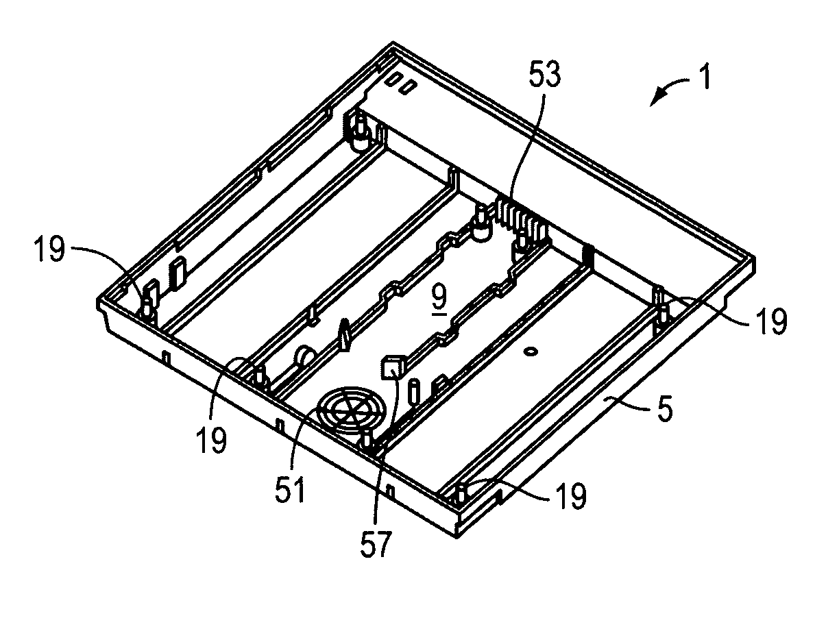
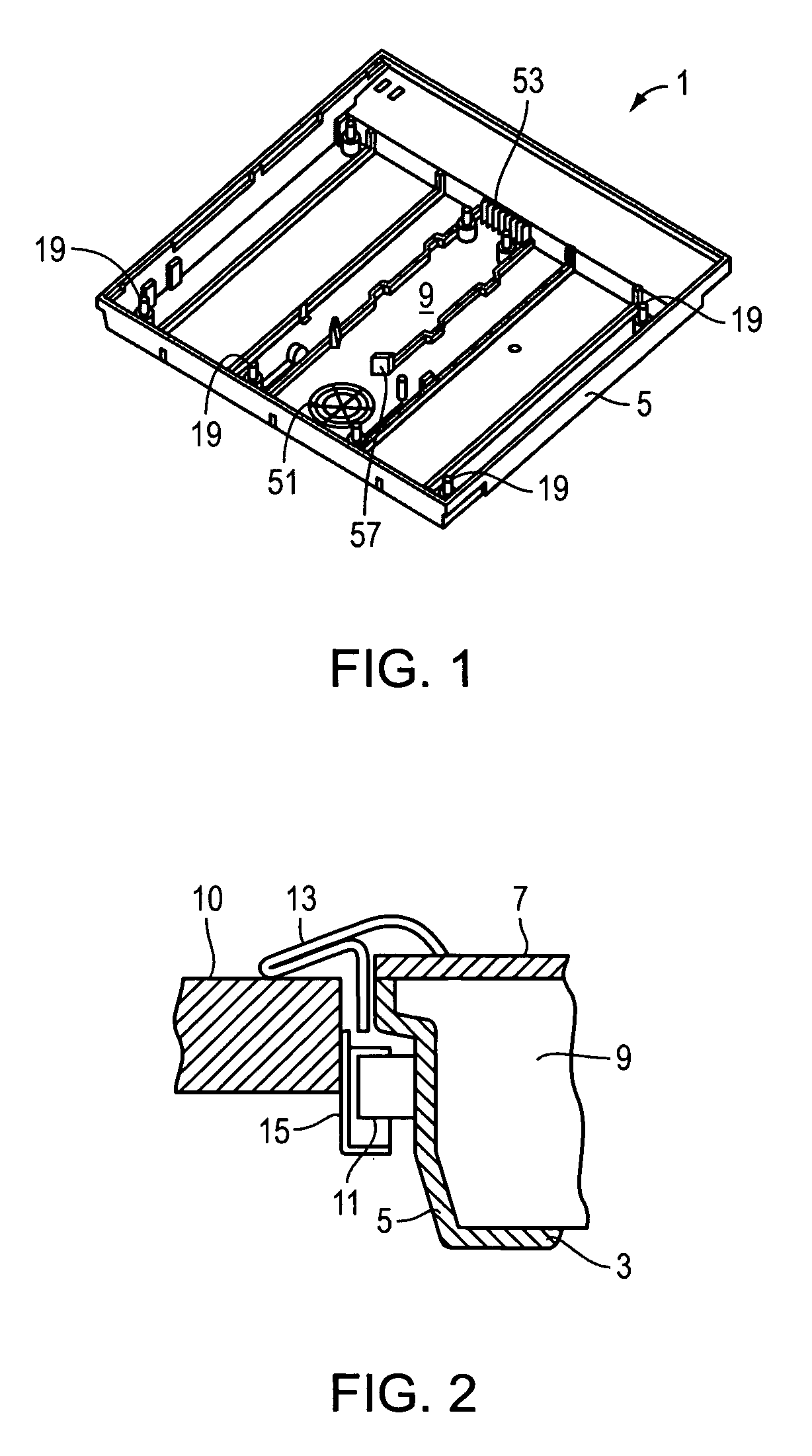
[0004]To attain the goals and avoid the disadvantages specified in the foregoing paragraphs, the invention comprises a hob with a hotplate, under which at least one induction mechanism is arranged, which is arranged in a housing, which housing has a housing floor and vertically projecting lateral walls connected to the hotplate, which delimit a housing interior, in which the induction mechanism is arranged.

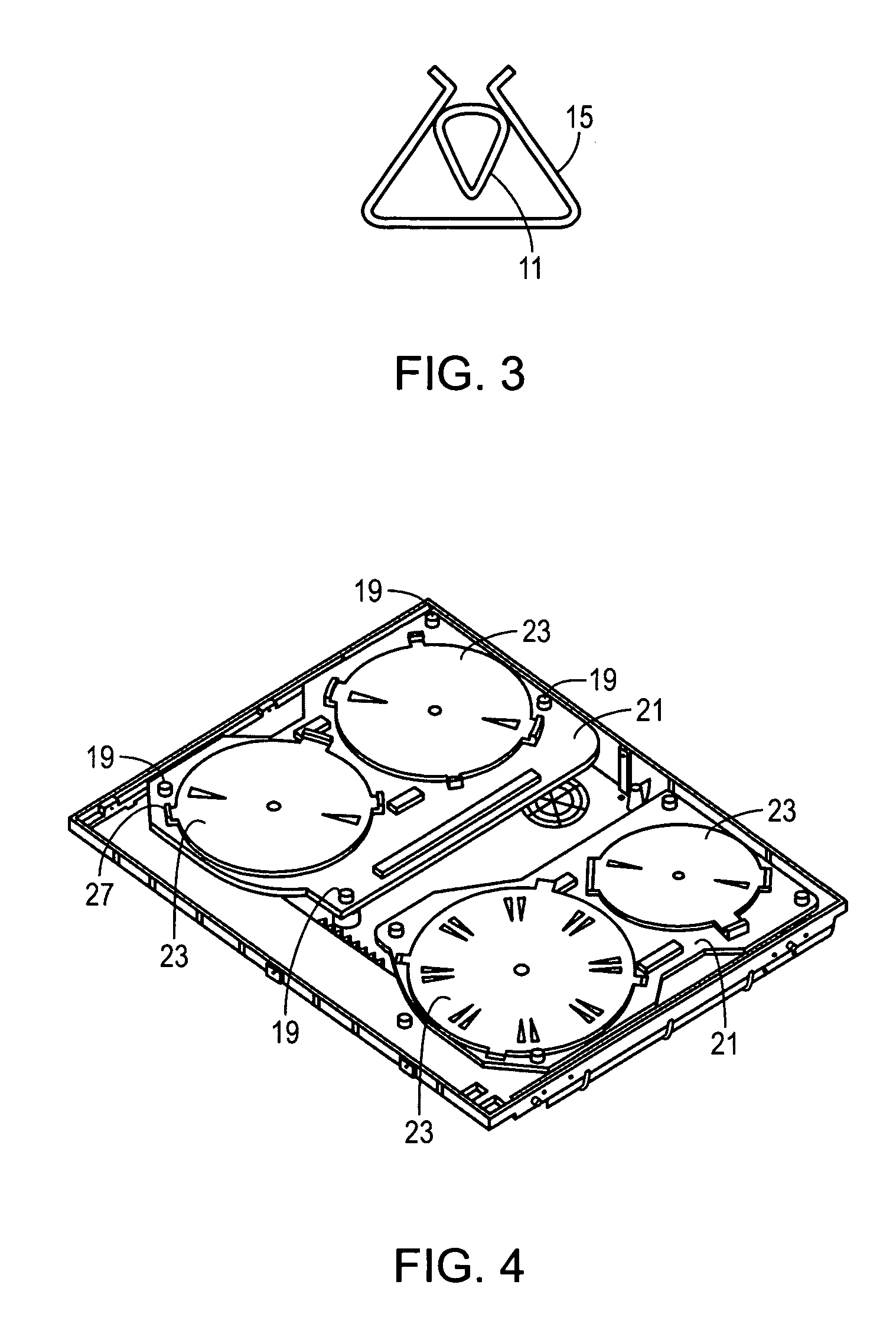
[0005]According to the present invention at least a partial region of the housing floor is designed as a monobloc plastic profile part.

[0006]According to the present invention the plastic profile part carries hob components of the induction mechanism.

[0007]According to the present invention the plastic profile part is connected to a hob frame.

[0008]By way of novelty the above mentioned housing according to the present invention is designed as a monobloc plastic profile part.

[0009]By way of novelty the shaping and / or material thickness of the plastic profile part according to the p...


PUM


Abstract

An induction hob comprising a hotplate, beneath which at least one induction mechanism is situated in a housing. The housing comprises a base and lateral walls that project vertically and are connected to the hotplate. The walls delimit an inner chamber of their corresponding housing containing the induction mechanism. At least one sub-section of the housing base is configured as a one-piece plastic section.

Description

OBJECT OF THE INVENTION[0001]The present invention relates to, as specified in the description, an induction hob, with which the production of the housing, including the induction mechanism and various structural parts, is to be simplified such that the housing can be manufactured in just a few working steps with a high degree of measuring precision.GENERAL PRIOR ART[0002]There are domestic induction hobs known, in which a container, which is arranged on the hotplate, is heated in complete absence of a heat source. In the case of these hobs a hotplate is provided, on which the containers to be heated are arranged, and under which at least one induction mechanism is provided, which is the main component, by means of which heating takes place. As with other types of hob, the corresponding hotplate is fixed in an opening of the work surface. The above mentioned structural parts and the induction mechanism are arranged in a housing, which has a floor connected to the hotplate and latera...

Claims


Application Information

Patent Timeline
Patent Type & Authority Patents(United States)
IPC IPC(8): H05B6/12
CPCH05B6/1263
Inventor ARNAL VALERO, ADOLFOFERRER SALILLAS, ALEJANDRO JESUS
Owner BOSCH SIEMENS HAUSGERATE GMBH
Why Eureka
Try Eureka