Light emitting diode traffic control device

a technology of traffic control and light-emitting diodes, which is applied in the direction of identification means, lighting and heating equipment, instruments, etc., can solve the problems of high cost of metropolitan and other political jurisdictions, insufficient light output, and permanent and unchanging natur

Inactive Publication Date: 2007-09-25
USA SIGNAL TECH
View PDF6 Cites 29 Cited by
  • Summary
  • Abstract
  • Description
  • Claims
  • Application Information

AI Technical Summary

Problems solved by technology

As such, they also account for high costs to metropolitan and other political jurisdictions that must procure, install, maintain, and replace such signal lamps.
Insufficient light output, flexibility in accepting various power sources, overheating, and susceptibility to damage or degradation due to short- or long-term subjection to transient power surges are just some of the issues that have been persistent problems in the field of signal lamps.
However, one drawback of conventional traffic signs is that they have a permanent and unchanging nature.
Inscribing such qualifications is fraught with two great limitations.
First, a traffic sign typically has a severely limited area within which to inscribe such a qualification.
Therefore, the inscribed qualification must be typeset using large letters, which even further limits potential content.
Consequently, the inscribed qualification cannot be easily changed on frequent basis.
However, such signs have encountered numerous problems, such as overheating, insufficient visibility, over-brightness in darkness, and unreliability.
The special lenses required by the signal lamp of FIG. 30 increase its cost, and other problems will also be apparent to those skilled in the art.
However, among the drawbacks of the signal lamp of FIG. 31 is that a special lens is required, thereby increasing cost of the system.
Furthermore, the LED signal lamp of FIG. 31 uses a relatively small number of LEDs, and thus could be subject to a corresponding reduction in reliability.
However, the signal lamp of FIG. 32, like those of FIGS. 1 and 2, requires a special lens, thereby increasing cost of the system.
Another problem that commonly occurs in the field of light emitting diode signal lamps is that when one or more light emitting diodes fail, the surviving light emitting diodes suffer accelerated aging as a direct result. FIG. 35 depicts a string of light emitting diode stages, including a first stage 48 and a second stage 50.
A problem of prior art light emitting diode signal lamps is that they pass current even after having failed.
As a result, the conflict monitor is not aware of such failures, and is hindered in taking appropriate action in response to failure of light emitting diode signal lamps.
In addition, some will fail before dimming sufficiently to require replacement.
Such failures not only have an immediately negative impact on the light output of the signal lamp, they can also result in the above-described accelerated degradation of the surviving LEDs.
However, such a blind replacement program does not adequately address signal lamps that fail prior to their scheduled replacement or signal lamps that would have significant useful life beyond their scheduled replacement.
In the former event, a dangerous situation could result from failure of an in-service signal lamp.
In the latter event, unnecessary costs are directly incurred.

Method used


Image

  • Light emitting diode traffic control device
  • Light emitting diode traffic control device
  • Light emitting diode traffic control device

Examples


Embodiment Construction

[0058]It will be understood by those skilled in the art that the present invention can be implemented in a number of different ways, within the scope of this application. A presently preferred embodiment of the invention will now be described below.

Overview

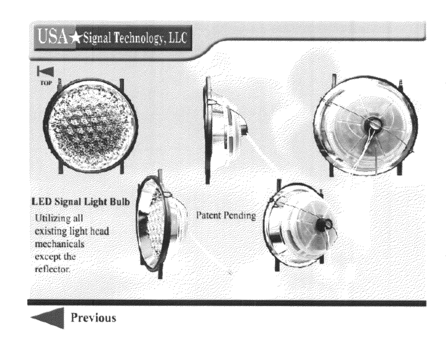
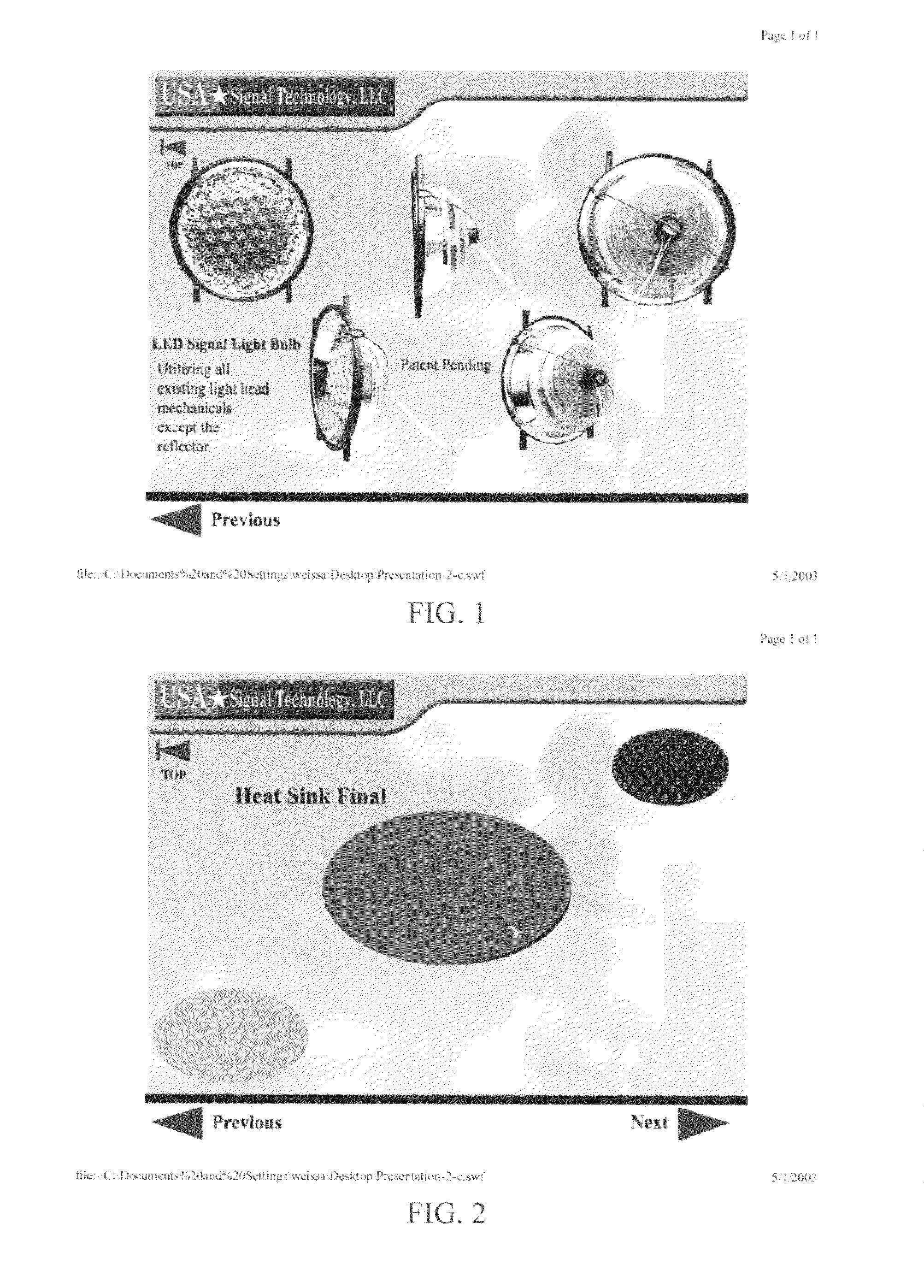
[0059]FIG. 1 shows a mostly assembled light emitting diode (LED) signal lamp from several angles, in accordance with an embodiment of the present invention. FIG. 1 shows a power supply assembly (having wires extending therefrom), an LED assembly (having a lens cover), and a chimney frame (having obvious apertures) mechanically connecting the two assemblies while leaving a chimney space ventilated between the heat sinks of the power supply assembly and the LED assembly so that the chimney space remains in fluid communication with the environment of the signal lamp. The apertures of the chimney frame can be best seen in the top center signal bulb and the bottom right signal bulb of FIG. 1.

[0060]FIGS. 27–29 show a schematic side view...


PUM


Abstract

A convection cooled traffic control device for selectively indicating traffic control guidance to vehicles. An enhanced brightness traffic control device for selectively displaying patterns of light emitting diodes (LEDs). A convection cooled traffic control device for selectively directing traffic by selectively actuating patterns of LEDs. A tapering system of a LED traffic control device. A brightness regulated LED traffic signal lamp. A conflict monitor interface system for a LED signal lamp. A failure logging method for compiling LED failures within an LED traffic signal light.

Description

[0001]Any reference cited hereafter are incoroporated by reference to the maximun extent allowable by law. To the extent a reference may not be fully incorporated herein, it is incorporated by reference for background purpose and indicative of the knowledge of one of ordinary skill in the art.CROSS-REFERENCE TO RELATED PATENT APPLICATIONS[0002]This patent application claims the benefit of:[0003]U.S. Provisional Patent Application No. 60 / 469,747, filed May 12, 2003, entitled “Light Emitting Diode Signal Lamp”;[0004]U.S. Provisional Patent Application No. 60 / 469,730, filed May 12, 2003, entitled “Light Emitting Diode Signal Lamp”;[0005]U.S. Provisional Patent Application No. 60 / 485,163, filed Jul. 3, 2003, entitled “Light Emitting Diode Signal Lamp”; and[0006]U.S. Provisional Patent Application No. 60 / 485,196, filed Jul. 7, 2003, entitled “Light Emitting Diode Signal Lamp”.TECHNICAL FIELD OF THE DISCLOSURE[0007]The present invention relates generally to the field of traffic control de...

Claims


Application Information

Patent Timeline
Patent Type & Authority Patents(United States)
IPC IPC(8): G08B5/22G08G1/095
CPCG08G1/095
Inventor STEVENSON, BOBCALIXTO, PAULLEE, HENRYCALIXTO, EDSONSANTANA, JORGEFERGUSON, RALPH
Owner USA SIGNAL TECH
Why Eureka
Try Eureka