Apparatus for determining the location of a pointer within a region of interest

a pointer and region technology, applied in the field of input systems, can solve the problems of increasing manufacturing costs, affecting the accuracy of calculation, and increasing the cost of consumers, and achieve the effect of maintaining the resolution of the apparatus and accurately calculating the cos

Active Publication Date: 2007-09-25
PIXART IMAGING INC
View PDF16 Cites 187 Cited by
  • Summary
  • Abstract
  • Description
  • Claims
  • Application Information

AI Technical Summary

Benefits of technology

[0042]The present invention provides advantages in that the non-reflective region provided near the corner of the region of interest inhibits the imaging device from seeing the true pointer merging with its double reflection. Also, providing the margin about the periphery of the region of interest inhibits the imaging device from seeing the true pointer merge with one or more other pointer reflections. By controlling merging so that the true pointer will not merge with pointer reflections, resolution of the apparatus is maintained.
[0043]The present invention provides further advantages in that since the mirrors are configured to aim reflected towards the active pixel sub-array of the imaging device, pointers appearing in the field of view of the imaging device can be detected and their positions relative to the touch surface calculated accurately.

Problems solved by technology

Although the above touch system works extremely well, the use of four digital cameras and associated digital signal processors to process image data captured by the digital cameras makes the touch system hardware intensive and therefore, increases the costs of manufacture.
This of course translates into higher costs to consumers.
Although this apparatus reduces hardware requirements since only one optical sensing device and processor are used, problems exist in that at certain locations within the active area, namely along the side edges and the corner diametrically opposite the detecting device, resolution is reduced.

Method used


Image

  • Apparatus for determining the location of a pointer within a region of interest
  • Apparatus for determining the location of a pointer within a region of interest
  • Apparatus for determining the location of a pointer within a region of interest

Examples


Embodiment Construction

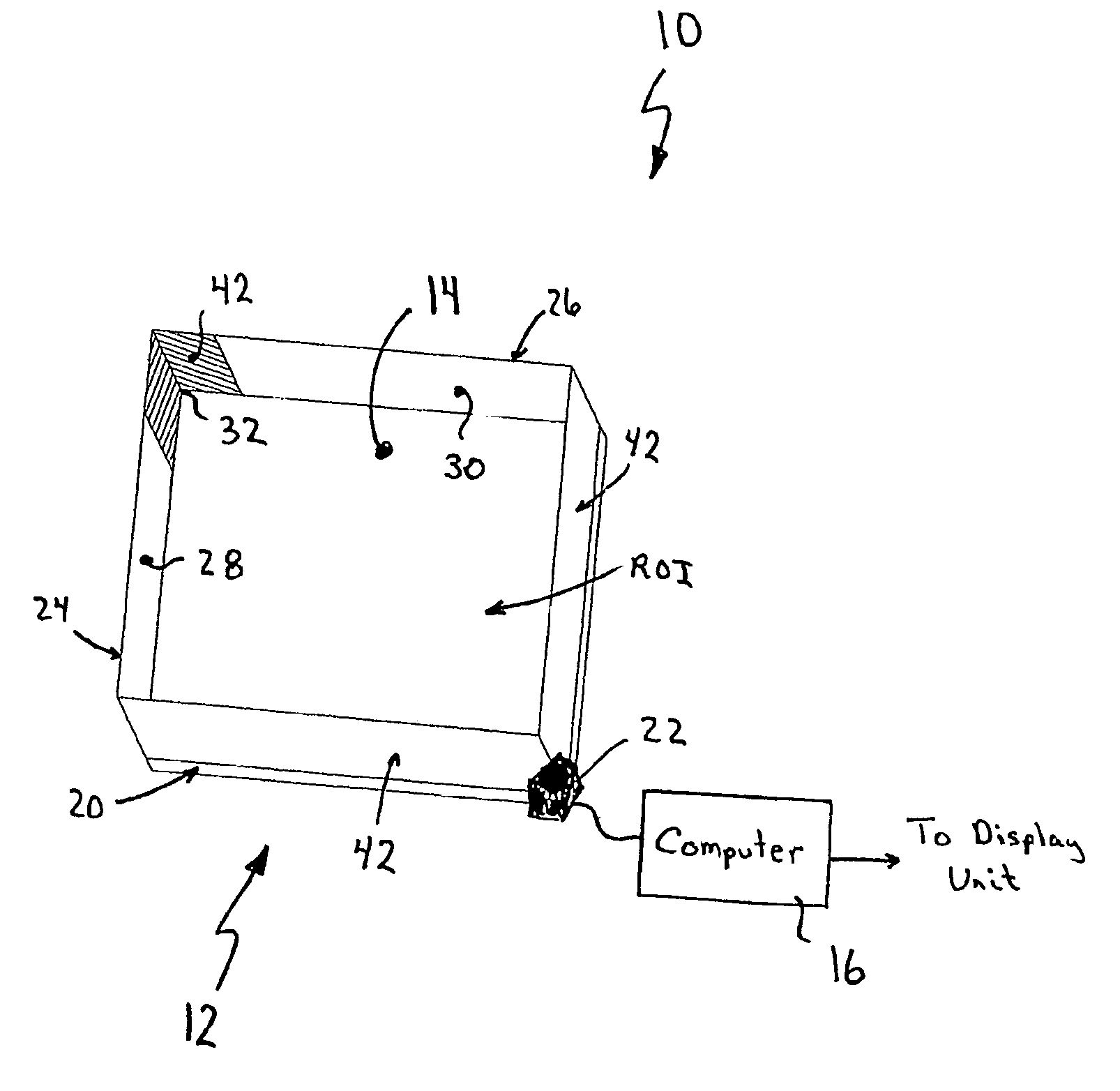
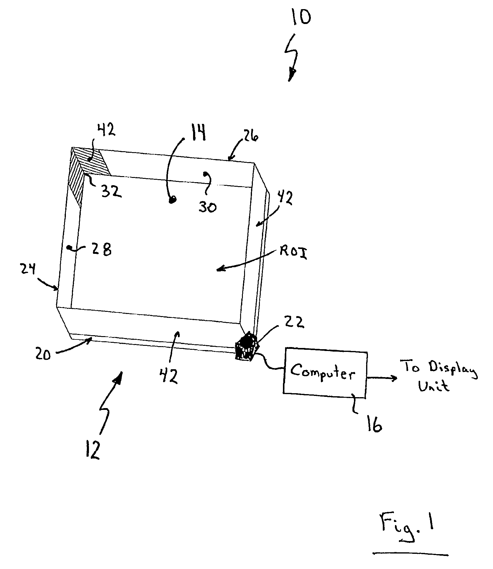
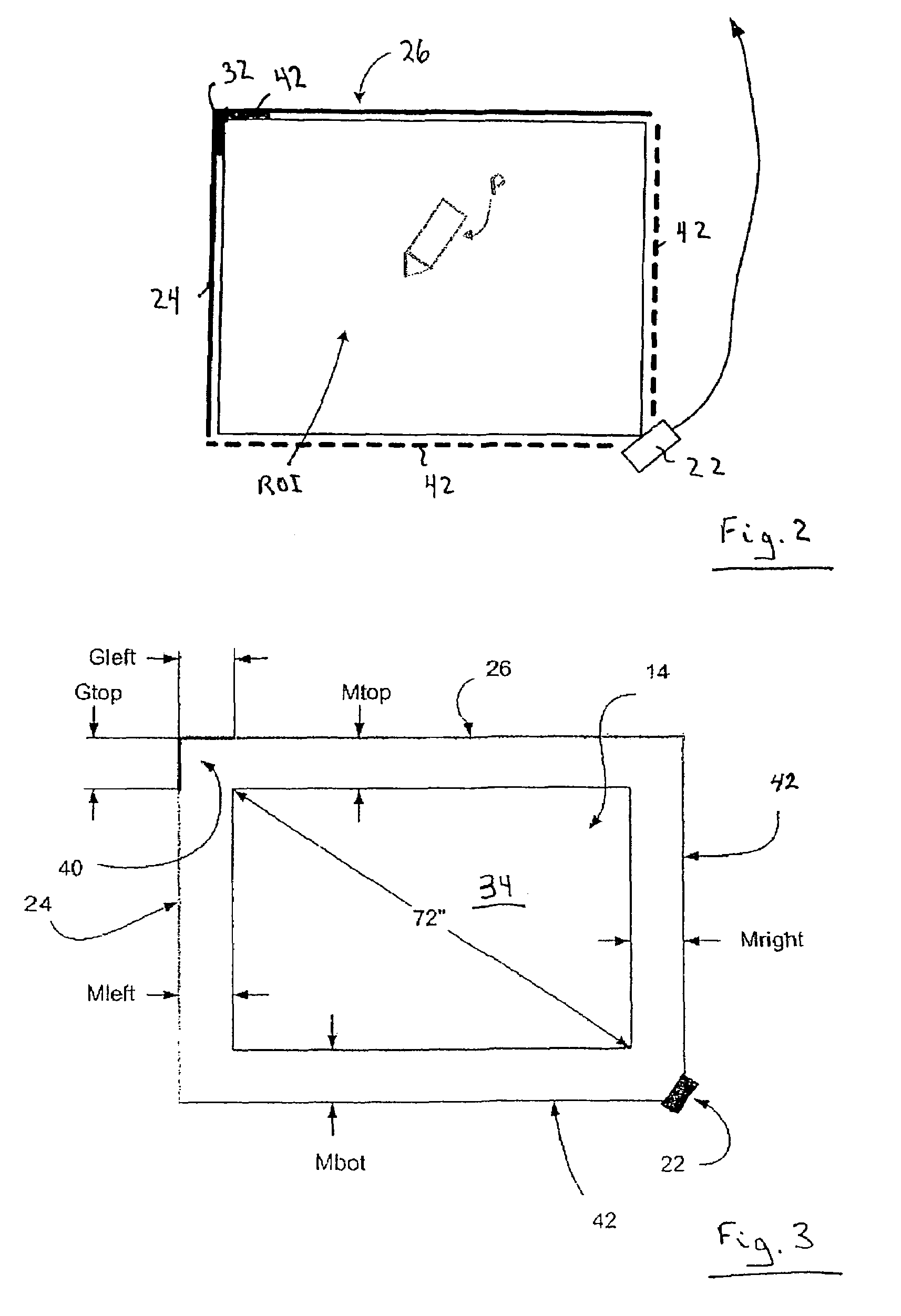
[0061]Turning now to FIGS. 1 to 3, an apparatus for determining the location of a pointer within a region of interest in accordance with the present invention is shown and is generally identified by reference numeral 10. In this particular embodiment, apparatus 10 is in the form of a touch system and is disposed over the display screen of a display unit such as a plasma television, front or rear projection screen or the like (not shown). As can be seen, apparatus 10 includes a generally rectangular assembly 12 encompassing a region of interest ROI and surrounding a transparent touch surface 14 that overlies the display screen. Assembly 12 communicates with a computer 16 executing one or more application programs. The computer 16 uses pointer data generated by the assembly 12 to update computer-generated images that are presented on the display screen. Pointer contacts on the touch surface 14 can therefore be recorded as writing or drawing or used to control execution of application ...


PUM


Abstract

An apparatus for detecting a pointer within a region of interest includes a first reflective element extending along a first side of the region of interest and reflecting light towards the region of interest. A second reflective element extends along a second side of the region of interest and reflects light towards the region of interest. The second side is joined to the first side to define a first corner. A non-reflective region generally in the plane of at least one of the first and second reflective elements is adjacent the first corner. At least one imaging device captures images of the region of interest including reflections from the first and second reflective elements.

Description

FIELD OF THE INVENTION[0001]The present invention relates generally to input systems and in particular to an apparatus for determining the location of a pointer within a region of interest.BACKGROUND OF THE INVENTION[0002]Touch systems are well known in the art and typically include a touch screen having a touch surface on which contacts are made using a pointer in order to generate user input. Pointer contacts with the touch surface are detected and are used to generate corresponding output depending on areas of the contact surface where the contacts are made. There are basically two general types of touch systems available and they can be broadly classified as “active” touch systems and “passive” touch systems.[0003]Active touch systems allow a user to generate user input by contacting the touch surface with a special pointer that usually requires some form of on-board power source, typically batteries. The special pointer emits signals such as infrared light, visible light, ultra...

Claims


Application Information

Patent Timeline
Patent Type & Authority Patents(United States)
IPC IPC(8): G06F3/042G06F3/041G06F3/033G09G5/08G01B11/03
CPCG06F3/0421
Inventor UNG, CHI MAN CHARLESBOOTH, DAVID KENNETHWORTHINGTON, STEPHENFLETCHER, MARK ANDREWSIROTICH, ROBERTO A. L.
Owner PIXART IMAGING INC
Why Eureka
Try Eureka