
Two-screen display device

a display device and two-screen technology, applied in the field of two-screen display devices, can solve the problems of increasing production costs, degrading image quality, and increasing production costs in order to increase the resolution of the display device, and achieve the effect of suppressing the increase of production costs

Active Publication Date: 2016-02-09
TRIVALE TECH LLC
View PDF55 Cites 6 Cited by
  • Summary
  • Abstract
  • Description
  • Claims
  • Application Information

AI Technical Summary

Benefits of technology

[0013]It is an object of the present invention to provide a two-screen display device, in which an increase of production cost can be suppressed while the same resolution as an image of a one-screen display device is maintained.
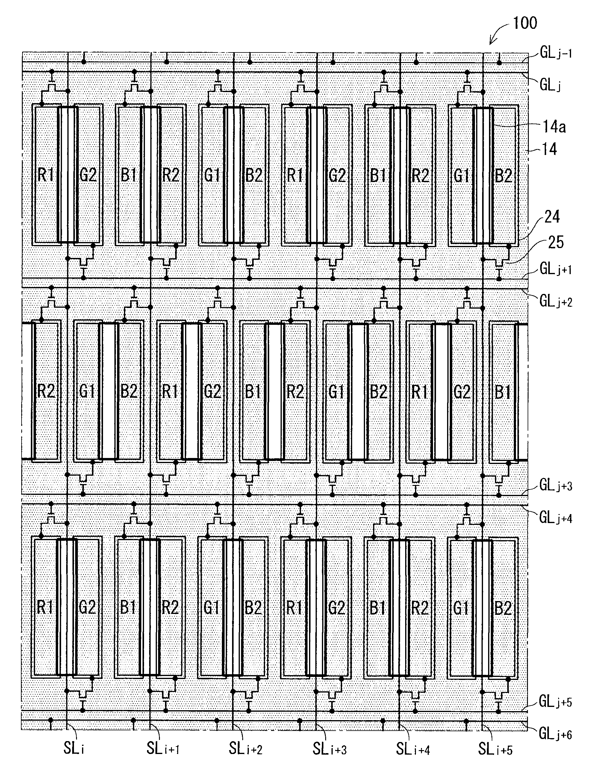
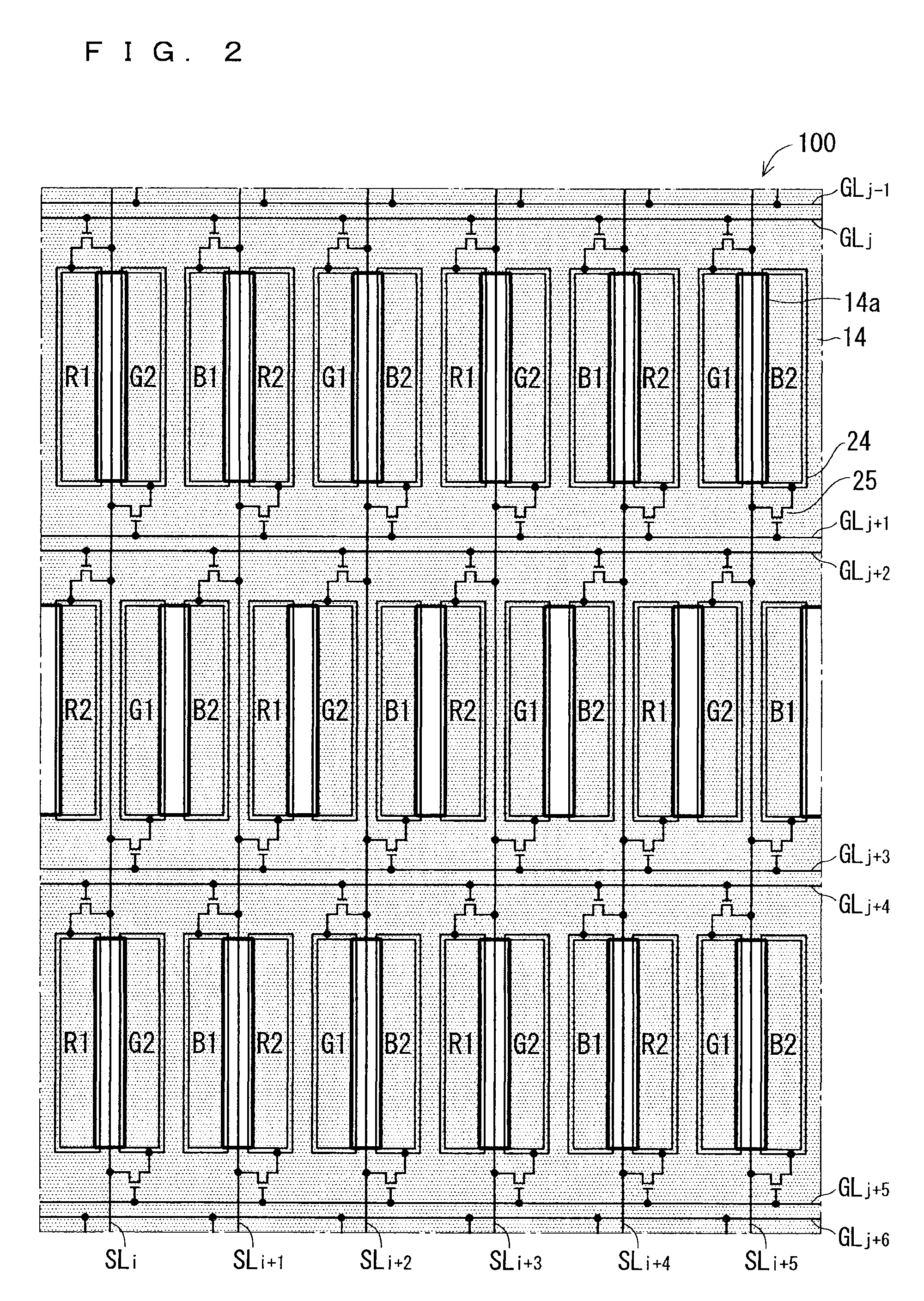
[0017]Although the vertical length of the sub-pixel is short, the horizontal width of the pixel is a half (three sub-pixel columns) of that of the background art by forming one pixel (color pixel) column using two sub-pixel rows, and the horizontal pitch of the pixel is a half of that of the background art. Therefore, the first image and the second image can be displayed with the same resolution as the one-screen display device. Because the width of the sub-pixel is equal to that of the background art, the distance between the pixel and the parallax barrier may be equal to that of the background art. Therefore, the production process for the display device of the background art can easily be applied to suppress the increase of the production cost.
[0019]Although the vertical length of the sub-pixel is short, the horizontal width of the pixel is a half (three sub-pixel columns) of that of the background art by forming one pixel (color pixel) column using two sub-pixel rows, and the horizontal pitch of the pixel is a half of that of the background art. The number of source lines is a half of that of the background art because of the configuration in which the image signal is supplied to the two sub-pixel columns from the one source line. Because the width of the sub-pixel is equal to that of the background art, the distance between the pixel and the parallax barrier may be equal to that of the background art. Therefore, the production process for the display device of the background art can easily be applied to suppress the increase of the production cost.

Problems solved by technology

Accordingly, resolution of the first image and resolution of the second image displayed by the two-screen display device become substantially a half of the resolution possessed by the display device, which results in degradation of image quality.
Therefore, a production cost increase is generated in order to increase the resolution of the display device.
For example, in the liquid crystal display device, when the distance between the parallax barrier and the pixel is defined by a thickness of a substrate (color filter substrate) on which a color filter or a black matrix is mounted, it is necessary to thin the substrate, and possibly a production process of the display device of the background art is hardly applied, which results in the production cost increase.

Method used


Image

  • Two-screen display device
  • Two-screen display device
  • Two-screen display device

Examples


first embodiment

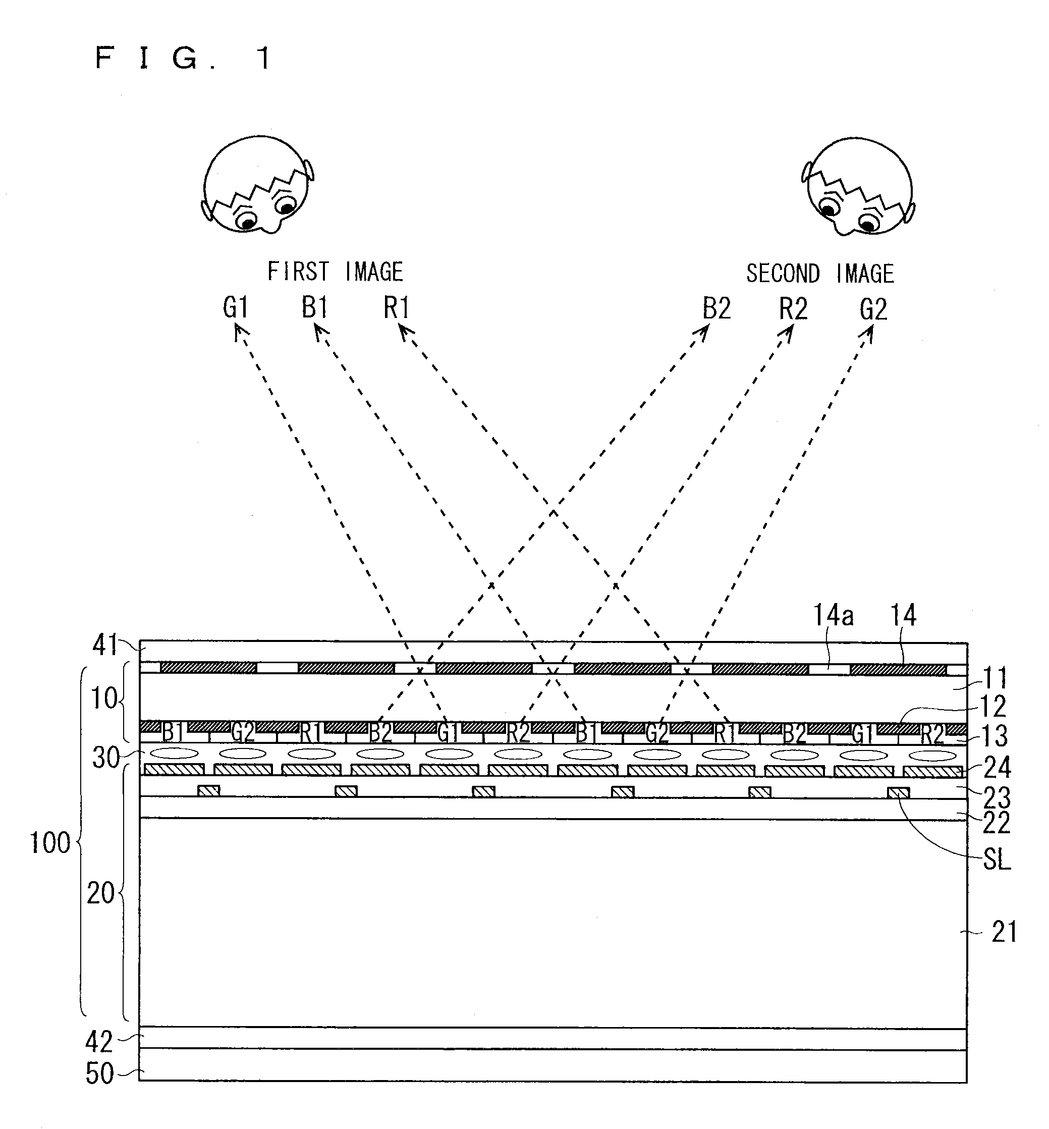
[0036]FIGS. 1 and 2 are views illustrating a configuration of a liquid crystal display device that is of a two-screen display device according to a first embodiment of the present invention. FIG. 1 is a sectional view of the two-screen display device, and FIG. 2 is a plan view of a liquid crystal display panel 100. At this point, a dual view liquid crystal display device that enables plural viewers to simultaneously view different images is displayed as an example of the two-screen display device.

[0037]As illustrated in FIG. 1, in the two-screen display device of the first embodiment, a liquid crystal display panel 100 and polarizers 41 and 42 that are provided on a front-surface side (visible side) and a rear-surface side are disposed on the front-surface side of the backlight unit 50. The liquid crystal display panel 100 is configured such that a liquid crystal 30 is interposed between a color filter substrate 10 on the front-surface side and a TFT array substrate 20 on the rear-s...

second embodiment

[0066]FIGS. 3 and 4 are views illustrating a configuration of a liquid crystal display device that is of a two-screen display device according to a second embodiment of the present invention. FIG. 3 is a sectional view of the two-screen display device, and FIG. 4 is a plan view of the liquid crystal display panel 100.

[0067]In the first embodiment, the first sub-pixels and the second sub-pixels are arrayed such that the color produced by each of the first sub-pixel and the second sub-pixel changes horizontally in each one sub-pixel. On the other hand, in the second embodiment, the first sub-pixels and the second sub-pixels are arrayed such that the color produced by each of the first sub-pixel and the second sub-pixel changes regularly in each two sub-pixels. Specifically, the first sub-pixel and the second sub-pixel, which receive the image signal from the same source line SL, are formed in the same color. Other configurations of the second embodiment are identical to those of the f...

third embodiment

[0072]FIG. 5 is a view illustrating a configuration of a liquid crystal display device that is of a two-screen display device according to a third embodiment of the present invention and a plan view of the liquid crystal display panel 100 of the two-screen display device.

[0073]In the third embodiment, the openings 14a of the parallax barrier 14 are arrayed not into the zigzag shape, but into the two-dimensional matrix shape. Specifically, all the openings 14a in the display region are provided on the source lines SL. All the openings 14a are disposed in the region between the first sub-pixel and the second sub-pixel, which receive the image signal from the same source line SL.

[0074]Other configurations of the third embodiment are identical to those of the second embodiment. However, as a result of the array of the openings 14a into the two-dimensional matrix shape, the row including only the first sub-pixels and the row including only the second sub-pixels are alternately arrayed in...


PUM

PropertyMeasurementUnit
aspect ratioaaaaaaaaaa
coloraaaaaaaaaa

Abstract

A two-screen display device, in which an increase of production cost can be suppressed while the same resolution as an image of a usual (one-screen display) device is maintained, is provided. In a liquid crystal display panel of the two-screen display device, each of a first sub-pixel for first image and a second sub-pixel for second image has an aspect ratio of about 6:1. A source line supplies an image signal to both the first sub-pixel and the second sub-pixel. Each row of the sub-pixel includes a gate line (first gate line) that drives the first sub-pixel and a gate line (second gate line) that drives the second sub-pixel. An opening of a parallax barrier is disposed in a region between the first sub-pixel and the second sub-pixel.

Description

BACKGROUND OF THE INVENTION[0001]1. Field of the Invention[0002]The present invention relates to a two-screen display device that displays two images in different directions.[0003]2. Description of the Background Art[0004]Recently, a Liquid Crystal Display (LCD) that can display a different image according to a viewing angle is becoming popular (for example, see “Dual-view liquid crystal and Triple-view liquid crystal,” Sharp Technical Journal, No. 96, November, 2007). Particularly, a two-screen display device that displays two images in different directions is applied to not only a dual-view display device that enables plural viewers to simultaneously view different images, but also a 3D display device that enables stereo display such that two images are viewed by eyes of the same viewer in consideration of a parallax (for example, see Japanese Patent Application Laid-Open No. 2009-250994 and International Patent Publication No. 2004 / 011987).[0005]As used herein, the “two-screen di...

Claims


Application Information

Patent Timeline
Patent Type & Authority Patents(United States)
IPC IPC(8): G09G3/36G09F19/14G02F1/13G02F1/1343H04N13/04G02B27/22G09F9/35G02B30/30
CPCG09G3/3614G02B27/2214G02F1/1323G02F1/1343G09F9/35G09F19/14G09G3/3648H04N13/0409G02F2001/134345H04N13/31G02F1/134345G02B30/30G02B30/27
Inventor NAKAYAMA, AKIOISHIKAWA, YOSHIMITSU
Owner TRIVALE TECH LLC
Learn More