Thermal printer and device and method for measuring resistance of heating element of thermal head of thermal printer

a technology of thermal printer and heating element, which is applied in the field of thermal printer, can solve the problems of counter circuit, inability to precisely reproduce the desired fine gradation, and inability to print images with imperfections

Inactive Publication Date: 2001-05-03
FUJIFILM CORP +1
View PDF0 Cites 5 Cited by
  • Summary
  • Abstract
  • Description
  • Claims
  • Application Information

AI Technical Summary

Problems solved by technology

7. In spite of such a fine control of heating or conduction time of the heating elements, the consequent image cannot exactly reproduce the desired fine gradation unless all the heating elements of the same thermal head have a completely uniform resistance.
For this reason, the printed images tend to have imperfections, such as chromatic unevenness.
However, with a sufficiently short

Method used


Image

  • Thermal printer and device and method for measuring resistance of heating element of thermal head of thermal printer
  • Thermal printer and device and method for measuring resistance of heating element of thermal head of thermal printer
  • Thermal printer and device and method for measuring resistance of heating element of thermal head of thermal printer

Examples


Embodiment Construction

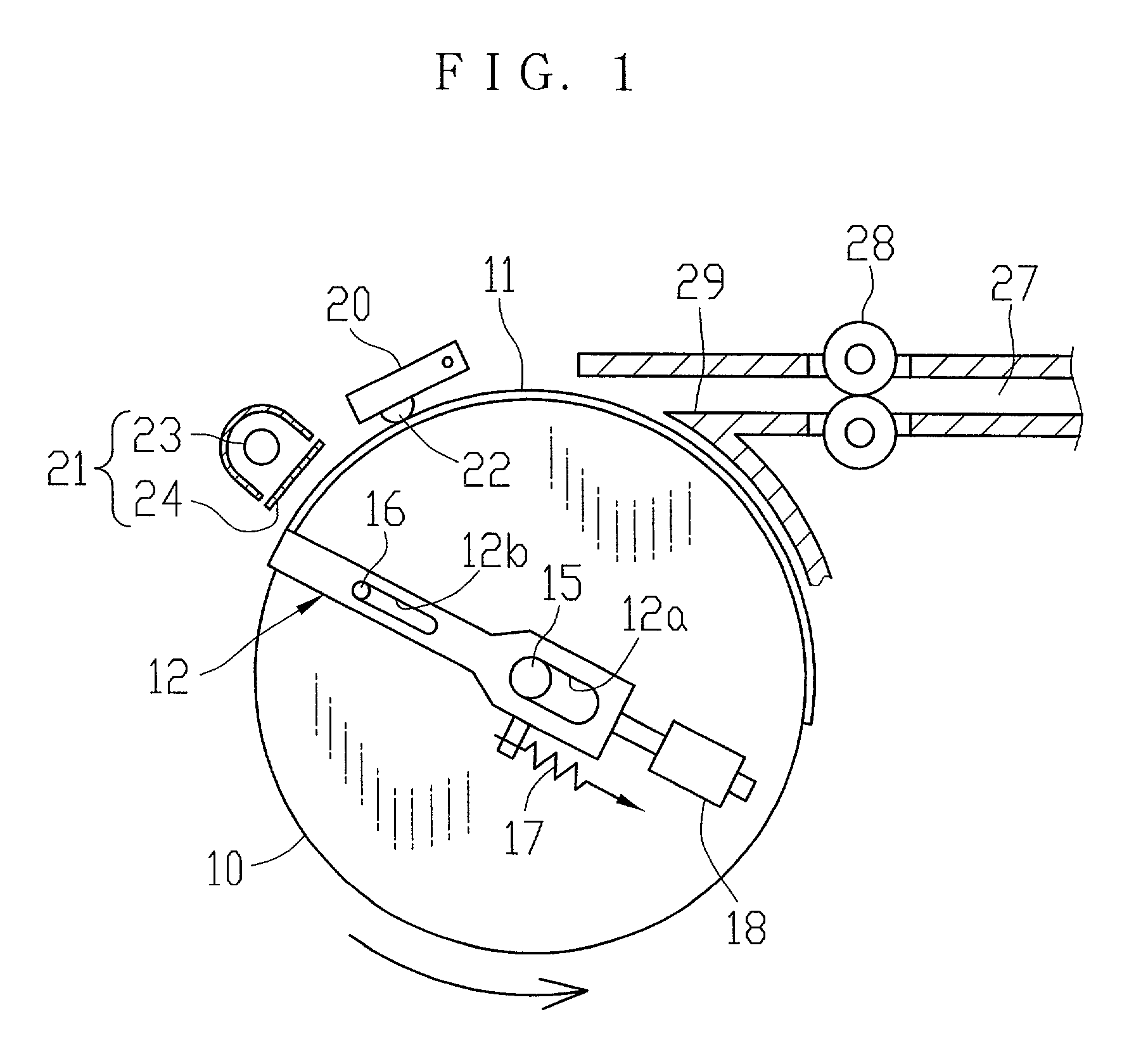
58. In FIG. 1 showing a thermosensitive color printer, a platen drum 10 carries a thermosensitive color recording paper 11 on the outer periphery thereof, and is rotated by a pulse motor (not shown) in a direction of an arrow during thermal recording. The platen drum 10 is provided with a clamp member 12 which secures the thermosensitive color recording paper 11 to the platen drum 10 at least at a portion, for example, at the leading end of the thermosensitive color recording paper 11. The clamp member 12 is of a channel shape having a clamp portion extending in an axial direction of the platen drum 10. Slots 12a and 12b are formed in either arm portion. The slots 12a are engaged with opposite ends of a drum shaft 15, and the slots 12b are engaged with guide pins 16 provided on both sides of the platen drum 10. The clamp portion of the clamp member 12 is usually pressed onto the platen drum 10 by a spring 17, and is removed off the platen drum 10 an act of a solenoid 18 when the the...


PUM


Abstract

A thermal head of a thermal printer is provided with an array of parallel connected heating elements and transistors connected in series to the heating elements in one to one relation. In a resistance measuring mode, one of the transistors connected to one heating element whose resistance is to measure is turned on, and other transistors are turned off. In this condition, a capacitor connected in parallel to the heating element is charged up to a predetermined voltage, and then discharged. A counter circuit starts time-counting by a short unit time t0 when a predetermined delay time Tmin has passed since the start of discharging, and outputs a count Q when the charged voltage goes down to a predetermined level. Based on a discharge time T=Tmin+t0.Q, the resistance of the heating element is calculated.

Description

1. 1. Field of the Invention2. The present invention relates to a thermal printer that forms an image by a thermal head having a plurality of heating elements, and more particularly to a device and a method for measuring resistance of the heating elements, for modifying image data so as to compensate for variations in resistance between the heating elements.3. 2. Background Arts4. As well known, thermal printers may be classified into thermal transfer printers and thermosensitive type printers. The thermal transfer printers use an ink film and transfers ink from the ink film onto a paper by heating the ink film. The thermosensitive type printers heat a thermosensitive recording medium directly to record an image thereon. To heat the ink film or the thermosensitive recording medium, the thermal printer use a thermal head with a linearly arranged array of large number of heating elements. The heating elements are constituted of resistors connected in parallel to one another.5. U.S. Pa...

Claims


Application Information

Patent Timeline
IPC IPC(8): B41J2/355
CPCB41J2/3553B41J2/3558
Inventor HAYASHI, JUNJI
Owner FUJIFILM CORP
Why Eureka
Try Eureka