
Monoblock double refraction image display device

An image display and birefringence technology, applied in optical components, optics, instruments, etc., can solve problems such as poor display quality, lengthened projection lens group distance, retinal detachment, etc.

Inactive Publication Date: 2005-01-26
吕兴增 +1
View PDF0 Cites 7 Cited by
  • Summary
  • Abstract
  • Description
  • Claims
  • Application Information

AI Technical Summary

Problems solved by technology

Moreover, in the process of quickly adjusting the focus, a large amount of blood flowing through the microvessels around the eyeball will cause pressure on the eyeball. The high intraocular pressure caused by long-term and frequent adjustment of the focus will not only cause discomfort to the human eye, In severe cases, there may be a risk of retinal detachment! Therefore, if this kind of real image projection device is applied to a glasses-type display device, when the observation time (within a few hours) is prolonged, the intraocular pressure of the observer will increase, resulting in symptoms of dizziness and discomfort, and even severe retinal detachment. Therefore, it is not suitable for young children or those with heart disease or high blood pressure
However, if the real image is projected on the eyeball, if the magnification is to be increased, the distance between the projection lens group and the eyeball needs to be lengthened. In this way, if the image magnification is to be increased, the space occupied by the projection system needs to be increased, which is not practical. Not practical
[0004] In addition, when the user's head moves, the display device that forms a projected real image in the eyes will produce image blur or severe shaking due to ghosting and Doppler effect, so the display quality is not good, and the application field is not wide.

Method used


Image

  • Monoblock double refraction image display device
  • Monoblock double refraction image display device
  • Monoblock double refraction image display device

Examples


Embodiment 1

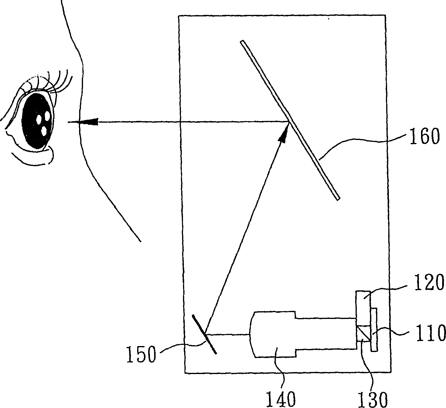
[0029] Please refer to Figure 8 , Figure 8 It is a sectional view of the inside of the glasses-type image display device of the present invention. The present embodiment comprises a T-shaped housing, containing an LCOS microdisplay 210, two light sources 211, two non-equal curvature convex lenses 220 and 221 (the first refracting lens group), two triangular mirrors 230 and 231 (the first reflector) unit), another two triangular prisms 240 and 241 (second reflection unit), two non-equal curvature convex lenses 250 and 251 (second refraction lens group), and two concave imaging regions 260 and 261 (virtual image imaging unit) through partial mirror surface treatment ). Wherein, the same side of the microdisplay 210 is provided with two convex lenses 220 and 221, and the other side of the two convex lenses 220 and 221 is provided with two triangular prisms 230 and 231, so that the convex lens 220 is between the display 210 and the triangular prism 230; And the two sides of t...

Embodiment 2

[0035] The structure of this embodiment is roughly the same as that described in Embodiment 1, except that the virtual image forming unit 260 is replaced by a flat mirror by a concave mirror. In this way, the formed image is only refracted and magnified by the convex lens 250 once, and then transformed into a virtual image by the plane mirror, which does not have the magnification function. However, the magnification and function of the structural image in this embodiment can still be accomplished by the convex lens 250 that refracts light.

Embodiment 3

[0037] The structure of this embodiment is roughly the same as that described in Embodiment 1, except that the virtual image imaging unit 260 is replaced by a concave lens with a reflectivity of 40% by a concave mirror; its imaging principle and magnification are the same as those described in Embodiment 1. But after replacing it with a concave lens, the observer can see the external environment at the same time when observing the image. And because the device of the present invention forms a virtual image by refraction projection, when a concave lens is used as the virtual image imaging unit, the light rays that transmit the concave lens have a relatively large angle of refraction and deflection. The person with the glasses-type display will not see the images and data that the user is using or receiving. It has good confidentiality and privacy, and will not interfere with other people around.


PUM


Abstract

A monomer bireflection image display device which comprises a display unit to provide an image; first refractor set located by one side of said display unit; first reflector unit located by the same side with said display unit to the first reflector set; second reflector unit and second refractor set located by one side of said reflector and two virtual image forming lens set located separately by the other two sides of second reflector set. The image displayed in the display unit is refracted into a handstand image through first refractor set and then to be reflected to second refractor set through first reflector set and second reflector unit and is reflected into real image with identical direction with original image through said refractor set and is converted into a virtual image with identical direction with original image by virtual image forming lens.

Description

technical field [0001] The invention relates to a single birefringence image display device, especially an image display device suitable for glasses type or head mounted type. Background technique [0002] In recent years, various audio-visual equipment and display devices have been improved with each passing day. In addition to enhanced functions, thin, light, small, and portable displays are also the mainstream of display development. One of the emerging display devices is virtual reality (virtual reality) technology. The integration of various technologies, such as display technology, computer technology, sensory technology, and sound effect technology, reduces the original large-sized audio-visual equipment to a square inch and becomes a portable glasses-type projection display device. Although the general flat panel display is light in weight, its size is limited by material weight and cost, and it cannot achieve the effect of enlarging the image size and being easy to ...

Claims


Application Information

Patent Timeline
IPC IPC(8): G02B27/01G02B27/12
Inventor 吕兴增胡锦标
Owner 吕兴增
Learn More