Defining link aggregation across a stack

Active Publication Date: 2007-09-25
CISCO TECH INC
View PDF12 Cites 73 Cited by
  • Summary
  • Abstract
  • Description
  • Claims
  • Application Information

AI Technical Summary

Benefits of technology

[0006]In one embodiment of the invention, a method of link aggregation allows port-aggregation

Problems solved by technology

Thus, in existing systems it is not possible to mark packets which belong to a link-aggregation group when they pass across the stack.
Accordingly,

Method used


Image

  • Defining link aggregation across a stack
  • Defining link aggregation across a stack
  • Defining link aggregation across a stack

Examples


Embodiment Construction

[0017]The invention will now be described with reference to several embodiments. One embodiment is described, by way of example, not limitation, in the context of switch hardware and a link aggregation protocol designed by the assignee of the present application. One of ordinary skill in the art will realize that the invention is applicable to other switching platforms and link aggregation protocols.

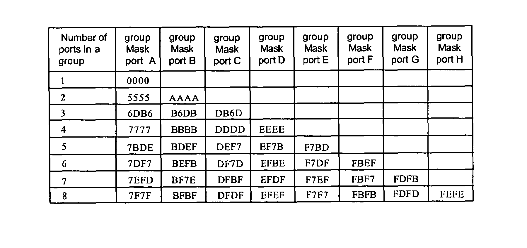
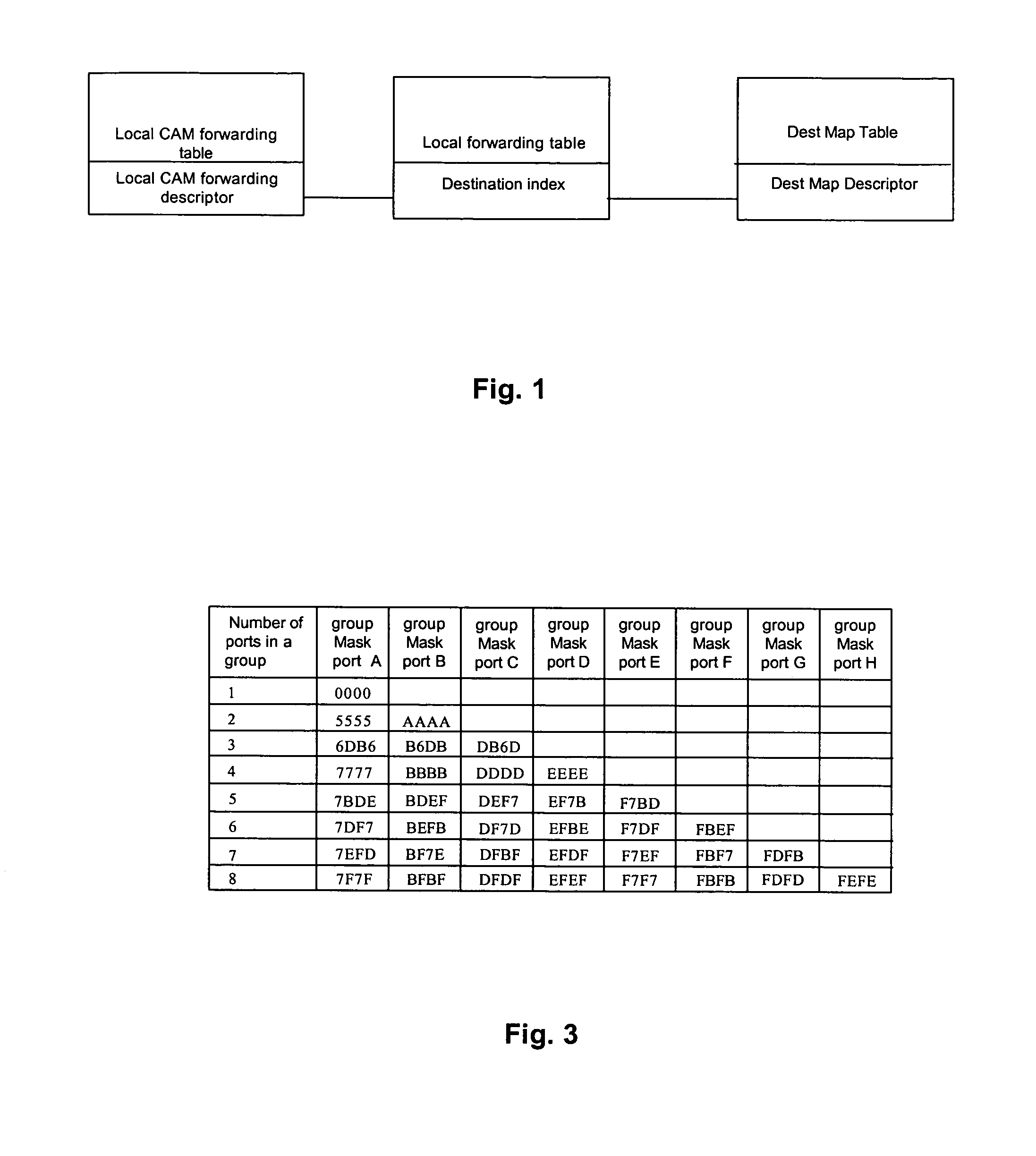
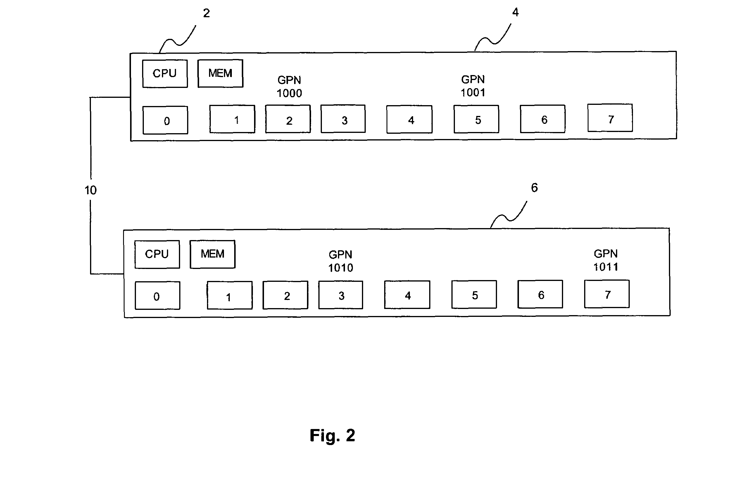
[0018]A flexible way to perform link aggregation on ports which do not reside in the same physical box in a stack will now be described. This embodiment allows a variable number of link aggregation groups where the number of groups is only limited by the total number of ports allowable in the stack. This embodiment also allows the number of ports being aggregated to be a non-multiple of two. In addition, it includes a numbering scheme for port identification which is efficient for systems which do searches and functions based on both the physical and logical port number.

[0019]In the cont...


PUM


Abstract

A cross stack port aggregation method and system associates a destination index with a received packet when it is provided to devices in the stack. Each device utilizes the destination index to access a descriptor identifying ports in the device included in the port aggregation group. An index generated from packet address data is used to select a bit in a group mask unique to each port.

Description

BACKGROUND OF THE INVENTION[0001]Link aggregation is the combination of multiple physical ports coupled to the same system or group of systems to form a group of ports which can be treated as one single higher bandwidth port. This Layer 2 feature is commonly referred to in products manufactured by the assignee of the present application as Etherchannel.[0002]In Etherchannel, and other link aggregation protocols, various physical ports in a switch are aggregated and mapped to a virtual port. High level switch management software is only aware of the virtual port. When a packet is transmitted from an egress virtual port, a port distribution protocol decides which one of the aggregated physical ports mapped to the virtual port is to transmit the packet. In conventional implementations of the distribution protocol the number of ports to be aggregated must be a power of two because the port selector is a binary number.[0003]Stacking is the ability to manage a group network devices, such ...

Claims


Application Information

Patent Timeline
IPC IPC(8): H04L12/56
CPCH04L45/245Y02B60/33Y02D30/50
Inventor CHENG, LINDAEMERY, SCOTTFINDLATER, STEWARTRIVERS, JAMES P.
Owner CISCO TECH INC
Why Eureka
Try Eureka