
Power saving control system and power saving control method

a power saving control and control system technology, applied in the field of power saving control system and power saving control method, can solve the problems of increasing the amount of data a current information society is required to handle, the inability to fully utilize energy saving mode, and the increase in the amount of data, so as to achieve the effect of improving energy-saving effect, sustaining energy-saving effect, and saving system energy consumption

Inactive Publication Date: 2007-09-25
FUJITSU LTD
View PDF22 Cites 21 Cited by
  • Summary
  • Abstract
  • Description
  • Claims
  • Application Information

AI Technical Summary

Benefits of technology

The present invention provides a power saving control method for data storage devices and electrical equipment that can effectively save energy while still meeting the requirements for quick response. The method involves classifying data storage devices and electrical equipment based on their required response speeds and setting them to power-saving modes of levels associated with the required response speeds. The method takes into consideration both the access frequency of data and the response speed required for the data to be handled. By implementing this method, a system can highly effectively save energy as a whole.

Problems solved by technology

An increase in the number of magnetic disk drives, or more particularly, an increase in the number of data storage devices capable of handling data online in real time leads to an increase in a power consumption.
However, the increase in the amount of data a current information society is required to handle is overwhelming the progress made by the energy saving technology.
Therefore, an energy saving mode cannot be utilized fully effectively.
This is because one data storage device cannot meet a performance-related requirement.
However, when the number of data storage devices is increased due to an increase in an amount of data, a power consumption required for waiting data to be received or to be transferred expands enormously.
The underlying problem of the classifying method has come to light from the viewpoint of environmental protection.
However, if data requires fast response though it is accessed less frequently, in this case, when only an access frequency is taken into consideration, as the data is stored in an HDD whose access frequency is low, a long time is required for starting the spindle motor.
This poses a problem in that the data cannot be accessed quickly.
When the data is moved to and stored in an HDD whose spindle motor is not rotating, an action cannot be performed within a required response time.
Moreover, it is hard to automatically identify a request for quick response through measurement performed by a data storage device.
Even when the contents of the patent publication describing an access frequency are broadly interpreted, the problem cannot be solved.

Method used


Image

  • Power saving control system and power saving control method
  • Power saving control system and power saving control method
  • Power saving control system and power saving control method

Examples


second embodiment

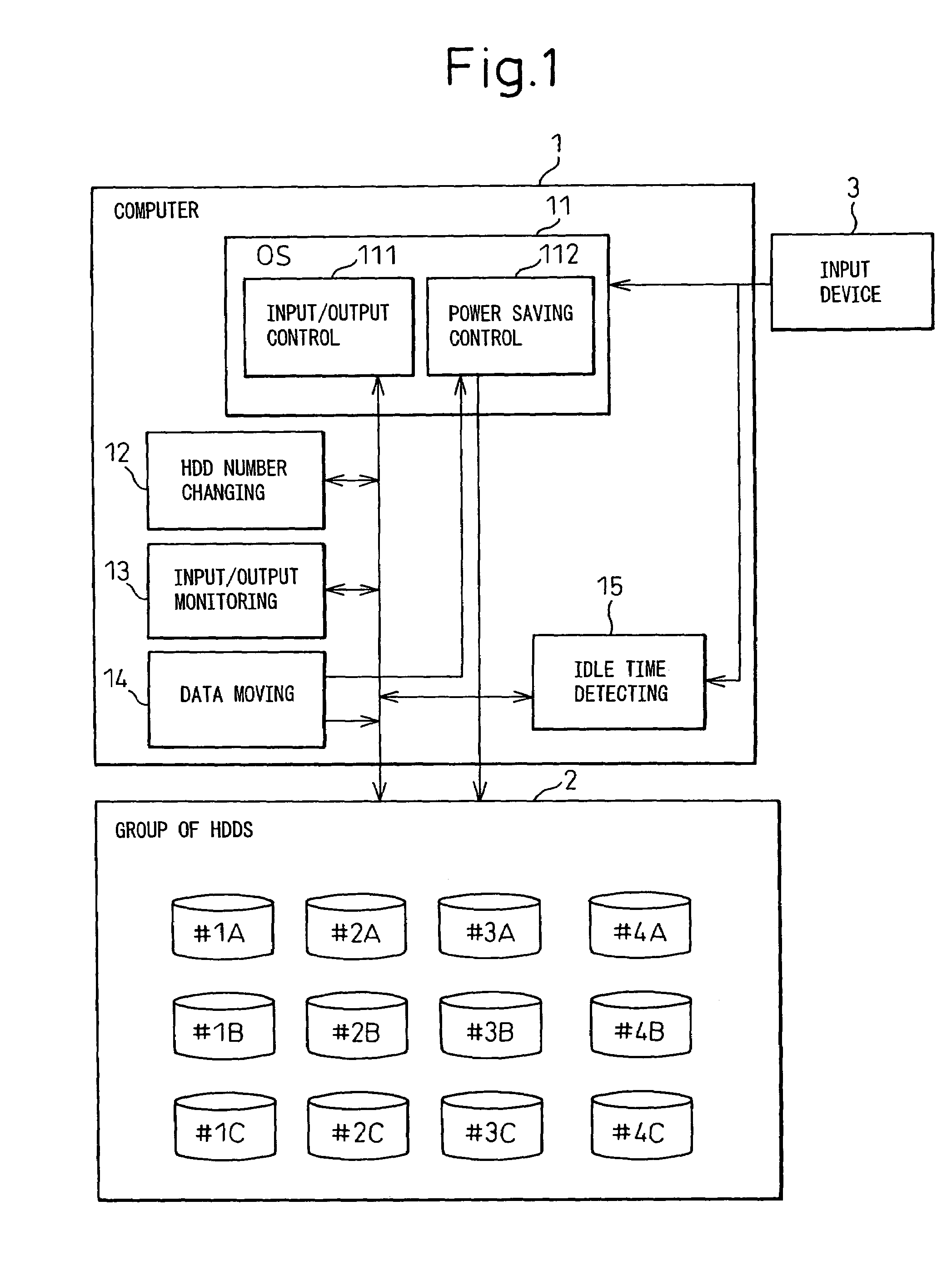
[0055]The data moving means 14 records the numbers of the HDDs to which respective data items are stored. when data is stored in an HDD which is included in the group 2 of HDDs and whose predefined required level of an access frequency is different from a measured required level of an access frequency of the data, the data moving means 14 moves the data to an HDD for which a required level of an access frequency is predefined to fall within a range including the measured value.

[0056]The idle time detecting means 15 included in the second embodiment of the present invention detects an idle time during which an input signal is not responded to and which is transferred from the input device 3 to the group 2 of HDDs.

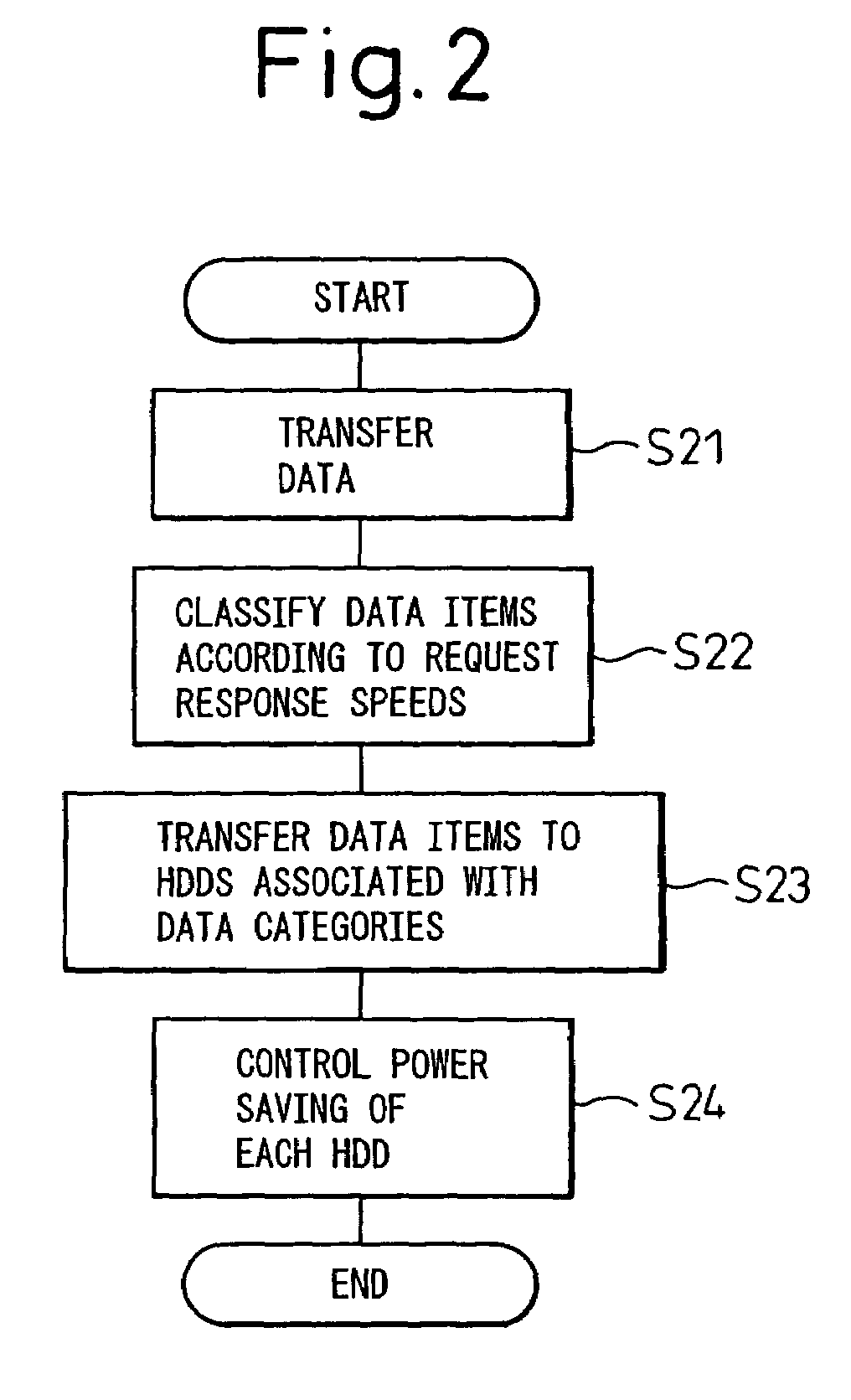
[0057]FIG. 2 is a flowchart outlining actions to be performed in the control system shown in FIG. 1. Referring to FIG. 2, the input device 3 transfers data to the computer 1 at step S21.

[0058]At step S22, data items are classified according to required response speeds. Acco...

first embodiment

[0067]FIG. 7 is a flowchart describing a power saving control method in accordance with the present invention. Referring to FIG. 7, data is transferred from the input device 3 to the computer 1 at step S71. At step S72, the input / output control means 111 checks the received data to see if a required response speed RS specified in the data falls below 0.1 sec. If the required response speed RS does not fall below 0.1 sec, whether the required response speed RS is equal to or higher than 0.1 sec and falls below 1 sec is verified at step S73. If the verification is made in the negative, whether the required response speed RS is equal to or higher than 1 sec and falls below 10 sec is verified at step S74.

[0068]If the required response speed RS is found to fall below 0.1 sec at step S72, the data is transferred to the first group of HDDs at step S75. The HDDs are, as listed in FIG. 8, set to the energy-saving mode 0.

[0069]If the required response speed RS is found to be equal to or highe...

third embodiment

[0088]Next, the present invention will be described below.

[0089]Talking of a required response speed and a predefined access frequency employed in the second embodiment, when the required response speed is changed, a user should merely modify a determined response speed. However, when an HDD is accessed, an access frequency is not always taken into consideration in order to transfer data. Therefore, an access frequency may be different from a set value in practice. According to the third embodiment of the present invention, if an access frequency classified by the control system of the second embodiment becomes different from a value measured by the input / output monitoring means 13, the data moving means 14 moves data from one HDD to another for which a predetermined access frequency is predefined. The HDD is then registered in the HDD changing means 12. Owing to the processing, energy saving can be controlled more finely and accurately.

[0090]Methods for controlling energy-saving mo...


PUM

PropertyMeasurementUnit
power consumptionaaaaaaaaaa
power consumptionsaaaaaaaaaa

Abstract

Provided is a power saving control method and system for data storage devices or electrical equipment. Herein, data items are divided into groups according to required response times or access frequencies. The groups of data items are allocated to data storage devices or pieces of electrical equipment. A data storage device or electrical equipment to which data that may be accessed using a long response time at a low access frequency is set to a power-saving mode of a higher level. Consequently, the data storage devices or pieces of electrical equipment are provided with power-saving features of different levels. Eventually, energy saving can be achieved more efficiently.

Description

CROSS-REFERENCE TO RELATED APPLICATIONS[0001]This application is a continuation application of PCT / JP02 / 12275 filed on Nov. 25, 2002, the contents being incorporated herein by reference.BACKGROUND OF THE INVENTION[0002]1. Field of the Invention[0003]The present invention relates to a power saving control system and a power saving control method that are adapted to a system comprising a plurality of electric devices for which different response speeds are required. More particularly, the present invention is concerned with a power saving control system and a power saving control method that are adapted to a system comprising a plurality of data storage devices.[0004]2. Description of the Related Art[0005]Along with the recent rapid innovation of information communication technologies, the information society has rapidly advanced and the amount of information to be handled has greatly increased. As a result of the popularization of the Internet, the amount of information to be handled...

Claims


Application Information

Patent Timeline
Patent Type & Authority Patents(United States)
IPC IPC(8): G06F1/26G06F1/30G06F1/32G06F3/06G11B19/00
CPCG06F1/30G06F1/3221G06F1/3268G06F3/0625G06F3/0634G06F3/0653G06F3/0676G11B19/00Y02B60/1246Y02D10/00
Inventor KAIJU, YOSHIHIKOYOSHIDA, SHOICHIMURAKAWA, YOSHITAKAFUTAMATA, AKIOITO, KATSUYOSHI
Owner FUJITSU LTD
Learn More