
Method and apparatus for burn-in of semiconductor devices

a technology of semiconductor devices and burnin, applied in the field of semiconductor devices, can solve the problems of increasing the size of memory arrays, increasing costs, and reducing reliability, and achieve the effects of reducing pin-count sockets, improving reliability, and saving costs

Active Publication Date: 2007-09-25
INTEGRATED DEVICE TECH INC
View PDF28 Cites 10 Cited by
  • Summary
  • Abstract
  • Description
  • Claims
  • Application Information

AI Technical Summary

Benefits of technology

[0006]The present invention provides a method and apparatus that requires fewer pins for burn-in of semiconductor devices having memory arrays. This results in reduced cost and increased reliability.
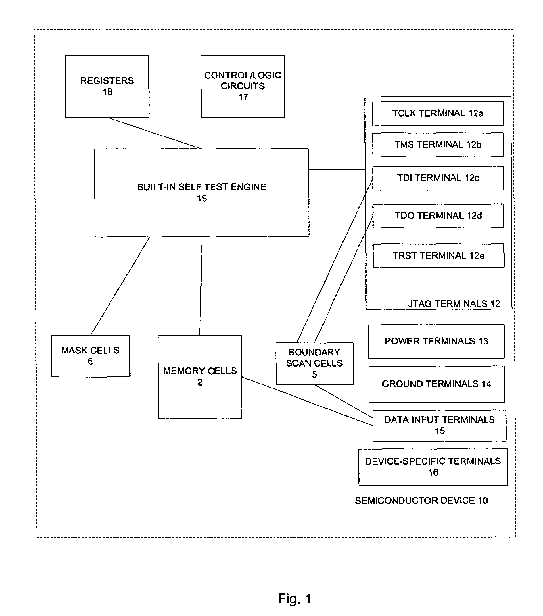
[0009]The present method does not require any data to be transmitted through data input terminals of the semiconductor device. Accordingly, the burn-in process of the present invention is not constrained by the size of the memory array of the device to be tested. Accordingly the apparatus and method of the present invention allow for burn-in of devices that include large memory arrays. Furthermore, significant cost savings are realized as reduced pin-count sockets can be used. In addition, as electrical contact is required with fewer pins than are required in prior art processes, reliability is improved.

Problems solved by technology

However, the size of memory arrays keeps increasing, resulting in the need to connect to more and more input data terminals of each memory array.
In order to assure good contact with all of the pins of the device under test more expensive sockets must be used, resulting in increased cost.
Moreover, as the pin-count increases, reliability decreases and the time required to perform each burn-in increases.
Also, the number of required connections is limited by the capabilities of the card-edge connector on the burn-in board that is used to connect to the burn-in driver.
With the high number of pin counts of recent semiconductor devices this will result in the need to buy new connectors and / or the need to reduce the number of sockets on a particular burn-in board.
In addition, a method and apparatus is needed that will meet the above needs and that is less expensive and more reliable.

Method used


Image

  • Method and apparatus for burn-in of semiconductor devices
  • Method and apparatus for burn-in of semiconductor devices
  • Method and apparatus for burn-in of semiconductor devices

Examples


Embodiment Construction

[0021]Reference will now be made in detail to the preferred embodiments of the invention, examples of which are illustrated in the accompanying drawings. While the invention will be described in conjunction with the preferred embodiments, it will be understood that they are not intended to limit the invention to these embodiments. On the contrary, the invention is intended to cover alternatives, modifications and equivalents, which may be included within the spirit and scope of the invention as defined by the appended claims. Furthermore, in the following detailed description of the present invention, numerous specific details are set forth in order to provide a thorough understanding of the present invention. However, it will be obvious to one of ordinary skill in the art that the present invention may be practiced without these specific details. In other instances, well-known methods, procedures, components, and circuits have not been described in detail so as not to unnecessarily...


PUM


Abstract

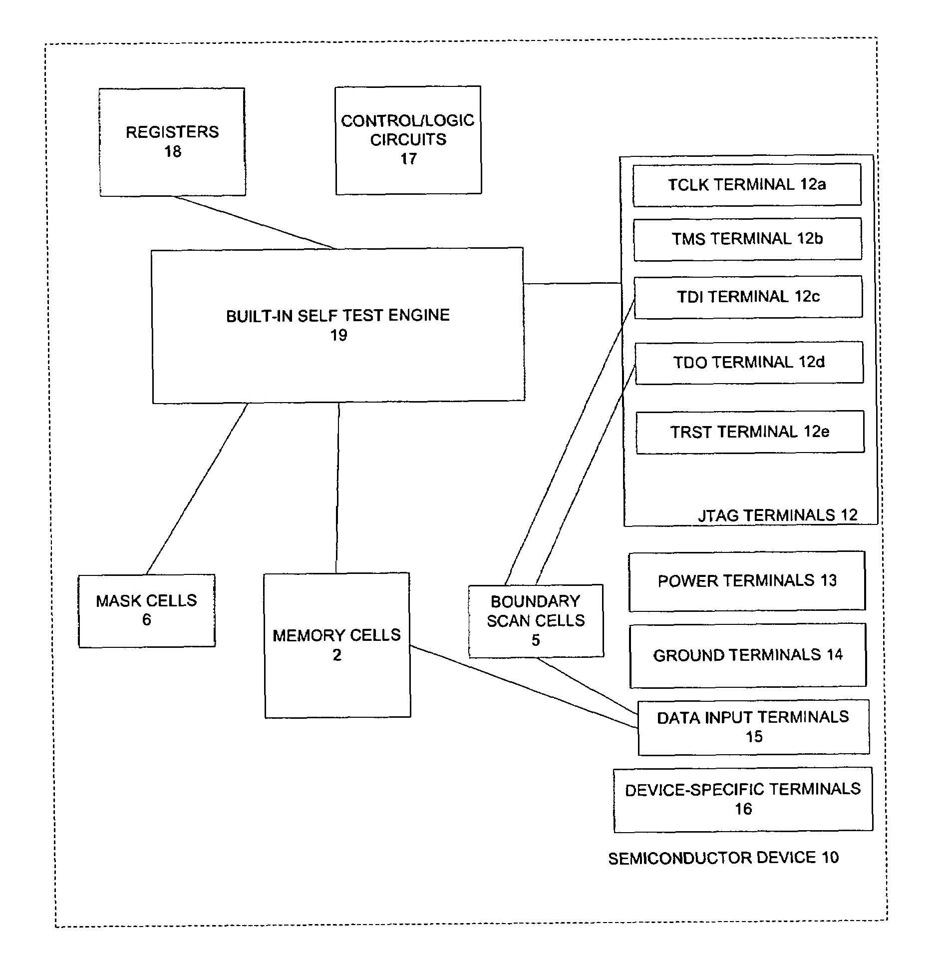
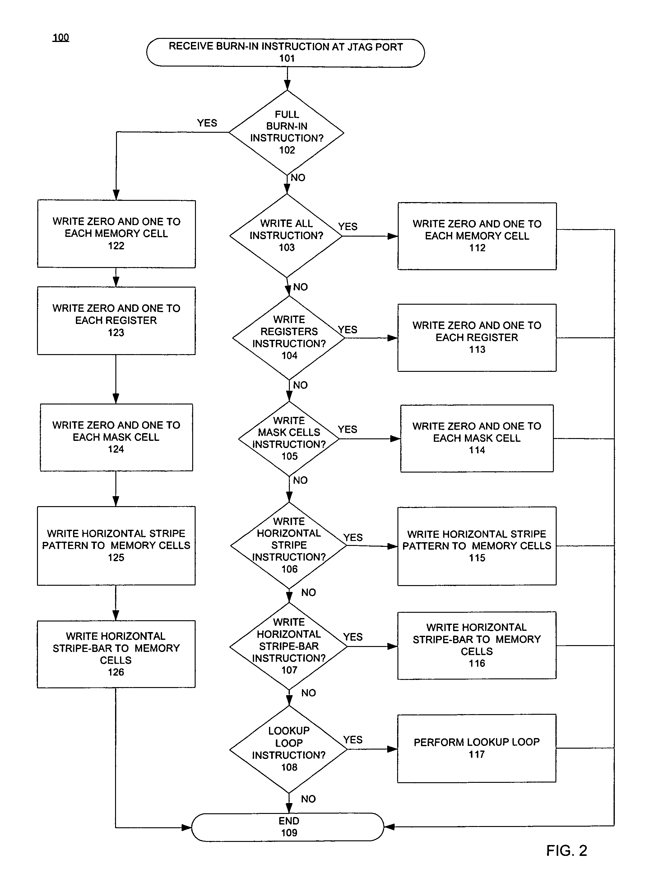
A method and apparatus for burn-in of semiconductor devices is disclosed. A semiconductor device that includes built-in self test circuitry is coupled to a socket on a burn-in board. The burn in board and the semiconductor device are heated. Burn-in instructions can be transmitted to the semiconductor device through a JTAG terminal of the semiconductor device. Upon receiving a burn-in instruction through a JTAG terminal, the built-in self test circuitry is operable to perform one or more burn-in function. This allows for burn-in of a semiconductor device without any transfer of data through the data input terminals of the semiconductor device.

Description

FIELD OF THE INVENTION[0001]The present invention relates to the field of semiconductor devices. More specifically, the present invention relates to burn-in and testing of semiconductor devices.BACKGROUND ART[0002]Burn-in operations are often performed on semiconductor devices to exercise and stress those circuits that may fail early in the product's life cycle. Conventional burn-in processes for devices that include memory arrays write data to each memory cell in the memory array. This is done using a socket that includes pins that electrically connect to each data input terminal of the memory array, and pins that electrically connect with other terminals required for the burn-in (e.g., power, ground, etc). This is a parallel process, with data transmitted in parallel to each data input terminal of each device under test.[0003]The types of inexpensive sockets typically used in burn-in testing have been adequate in the past as there has not been a need to connect to a large number o...

Claims


Application Information

Patent Timeline
IPC IPC(8): G11C29/10G11C29/02
CPCG11C29/06G11C15/00G11C29/12G11C2029/5602
Inventor SOBAITI, MOUSSASHRANK, ROBERTREDDY, SUDHAKARJIRJIS, YOUSIF
Owner INTEGRATED DEVICE TECH INC
Learn More