Automatic speed calculation for scratch machine

a technology of automatic speed calculation and scratch machine, which is applied in the direction of mechanical means, instruments, manufacturing tools, etc., can solve the problems of testing speed deviation from an acceptable value, and achieve the effect of accurate test speed and improved results

Inactive Publication Date: 2007-10-02
TOYOTA MOTOR CO LTD
View PDF6 Cites 7 Cited by
  • Summary
  • Abstract
  • Description
  • Claims
  • Application Information

AI Technical Summary

Benefits of technology

[0009]A method of performing a scratch test on a surface of a material at an acceptable test speed includes providing a blade in contact with the surface, applying a load on the blade directed against the surface, providing a lateral force (such as derived from hydraulic pressure within a cylinder) to urge the blade across the surface at a test speed approximately correlated with the force, accurately determining the actual test speed (rather than an estimated value obtained from the magnitude of the lateral force) using an electronic timer, and adjusting the lateral force if the test speed is not within an acceptable range of test speeds. The lateral force adjustment can be automatically controlled, using the test speed measurements, to provide an acceptable test speed over a wide range of loads. For example, hydraulic pressure to a cylinder can be adjusted using a fluid valve, such as a pressure regulator, to an extent necessary to provide an acceptable test speed.

Problems solved by technology

However, variable loading of the arm often causes the test speed to deviate from an acceptable value.

Method used


Image

  • Automatic speed calculation for scratch machine
  • Automatic speed calculation for scratch machine
  • Automatic speed calculation for scratch machine

Examples


Embodiment Construction

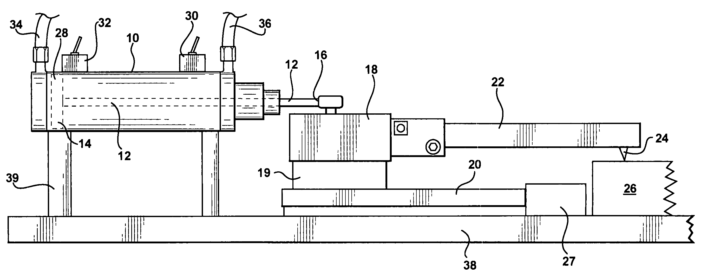
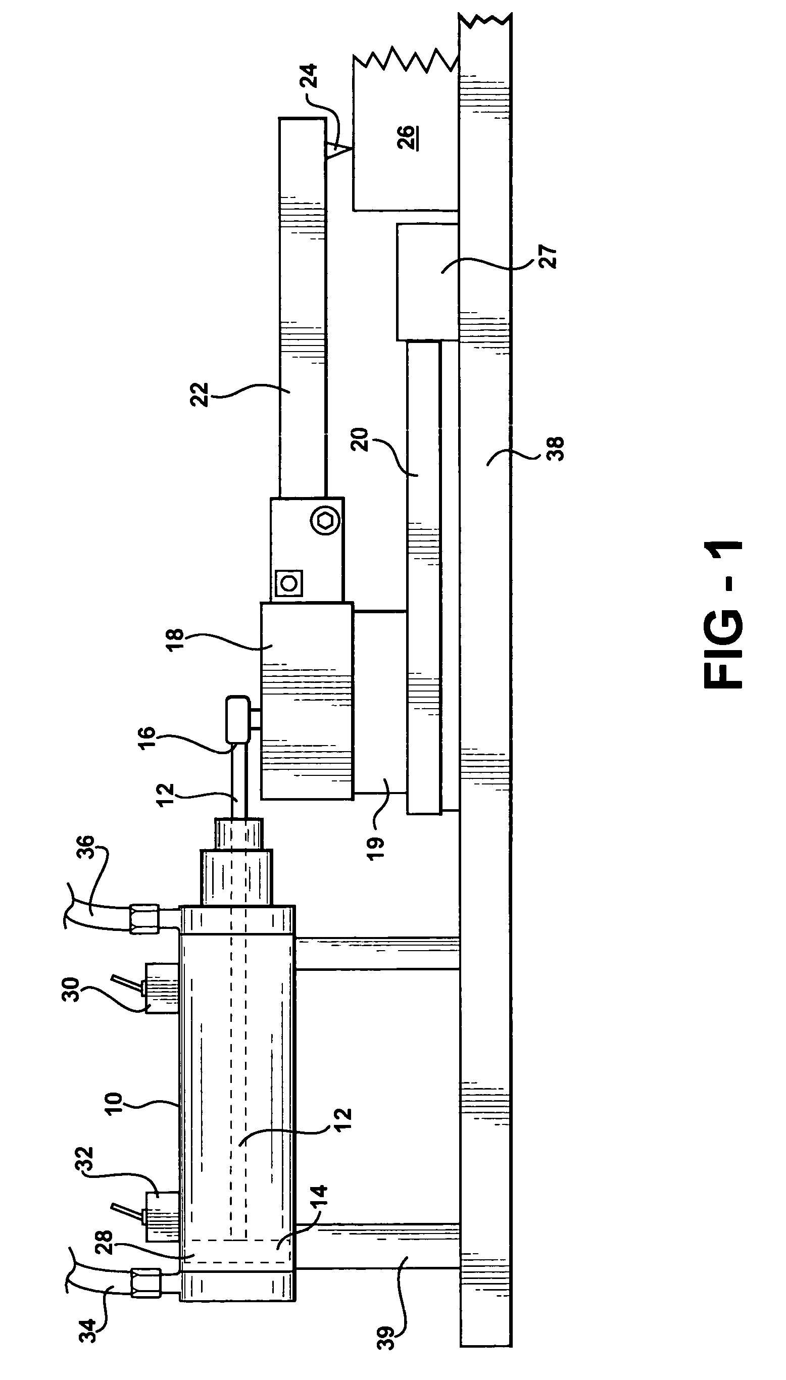
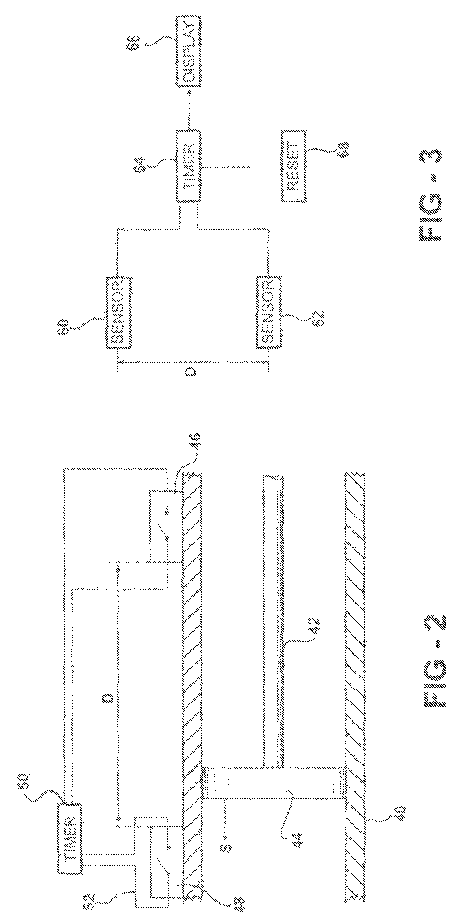
[0014]An improved surface testing machine includes a timing mechanism that allows accurate determination of the true test speed during a scratch test or other surface test. The test speed is the speed across the surface of a surface contacting element, such as a blade of a scratch test machine. The test speed can be determined by determining the speed of other components mechanically coupled to the surface testing components, such as the speed of a piston.

[0015]For example, uncertainty in scratch test results arises from test speed variations between scratch tests. Conventional machines allow a crude speed control through adjustment of air or other hydraulic fluid pressure to a drive cylinder. However, different loadings of the test arm (or arms) cause test speed variations.

[0016]The conventional approach to adjusting test speed is to adjust the urging force, such as hydraulic pressure, urging the blade over the surface. The actual test speed, however, depends on various parameters,...


PUM

PropertyMeasurementUnit
surface testaaaaaaaaaa
speedaaaaaaaaaa
magneticaaaaaaaaaa

Abstract

An improved surface testing apparatus, such as a scratch test apparatus, allows accurate determination of the test speed, for example using one or more magnetic sensors. An example scratch test apparatus comprises an arm assembly, and an attached blade moving over the surface during the scratch test. A pair of spaced apart reed switches are provided proximate to the arm assembly, the reed switches being successively actuated by a magnetic portion of the arm asssembly as it moves during the scratch test.

Description

FIELD OF THE INVENTION[0001]The present invention relates to apparatus and methods for material testing, in particular surface testing, such as scratch testing.BACKGROUND OF THE INVENTION[0002]In order to test the wear resistance of a sample material, such as plastic, resin, or other material, a blade can be dragged across the surface of the sample. The depth and visibility of the scratches can be judged to determine which material is more resistant to scratching.[0003]An example conventional scratch test machine includes five blades, each blade attached to a metal arm, is pulled across the surface of a sample. The design allows different loads to be placed on the arms, in order to determine at which load the sample scratches. In a conventional scratch test machine, hydraulic pressure within a cylinder is adjusted so as to approximately determine the test speed. However, such scratch tests are often irreproducible. Improved surface testing machines are required, in order to obtain m...

Claims


Application Information

Patent Timeline
Patent Type & Authority Patents(United States)
IPC IPC(8): G01N3/46G01N33/00
CPCG01N19/02G01N3/46
Inventor HICKS, DAVID L.NIEL, MICHAEL J.
Owner TOYOTA MOTOR CO LTD
Why Eureka
Try Eureka