Ozone-based conveyor cleaning system

Active Publication Date: 2007-10-02
OZONE INT +1
View PDF31 Cites 19 Cited by
  • Summary
  • Abstract
  • Description
  • Claims
  • Application Information

AI Technical Summary

Benefits of technology

[0006]A high-pressure rinser may also be positioned over the treating section such that the distributor is positioned between the high-pressure rinser and the processing region. The rinser removes grease and soil prior to deposition of a fresh layer of ozonated water on the conveyor belt.
[0007]Ozonated water may be generated by a system including first and second tanks. The first tank is filled with ozone gas

Problems solved by technology

This collection of soil and grease is extremely unsanitary and degrades the aesthetic appearance of the plant.
Plant operators therefore risk being reprimanded, fined, or shut down by the on-site USDA inspector.
Furthermore, the longer the greas

Method used


Image

  • Ozone-based conveyor cleaning system
  • Ozone-based conveyor cleaning system
  • Ozone-based conveyor cleaning system

Examples


Embodiment Construction

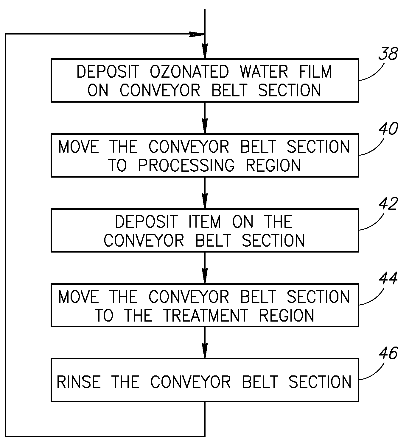
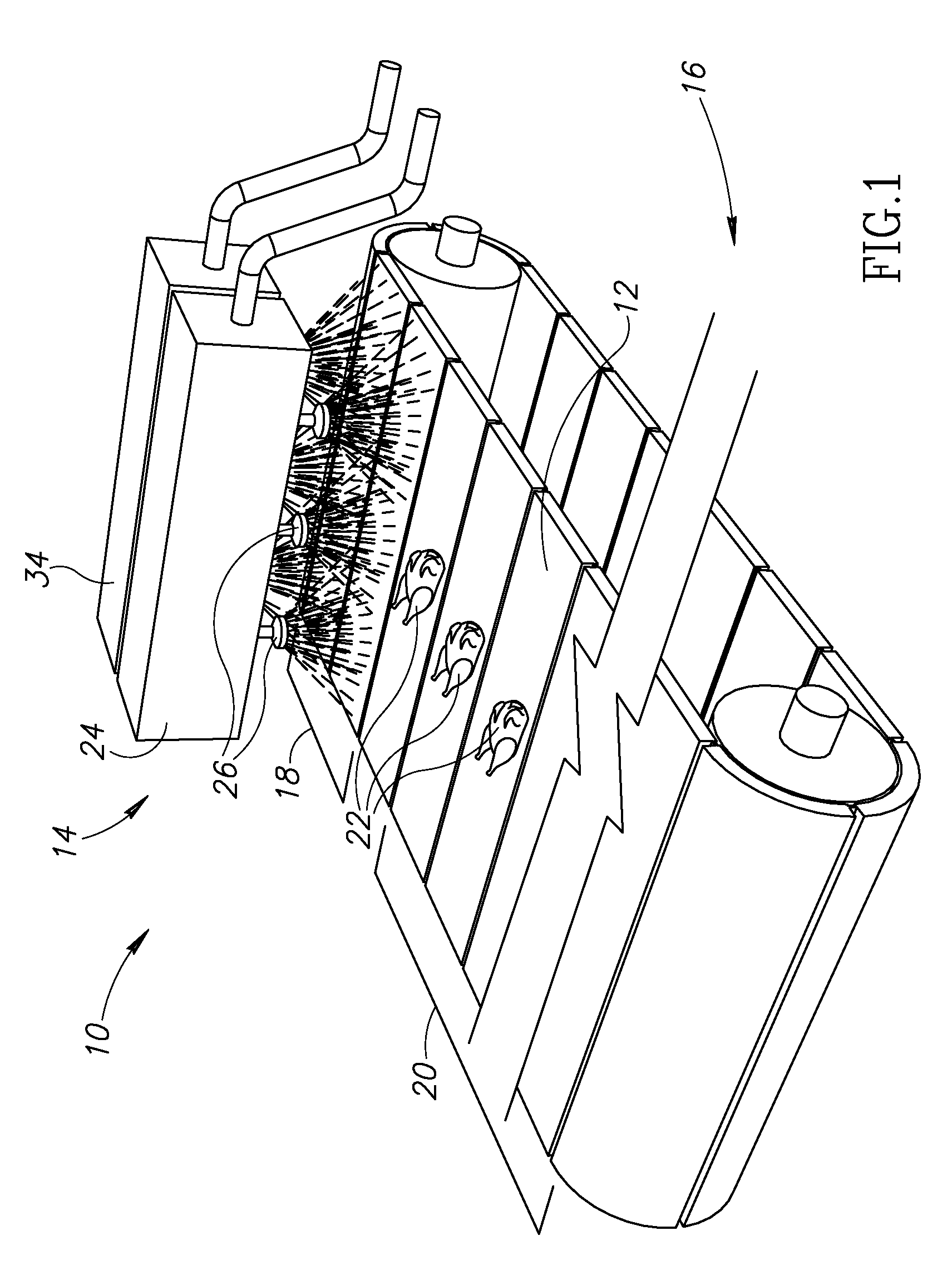
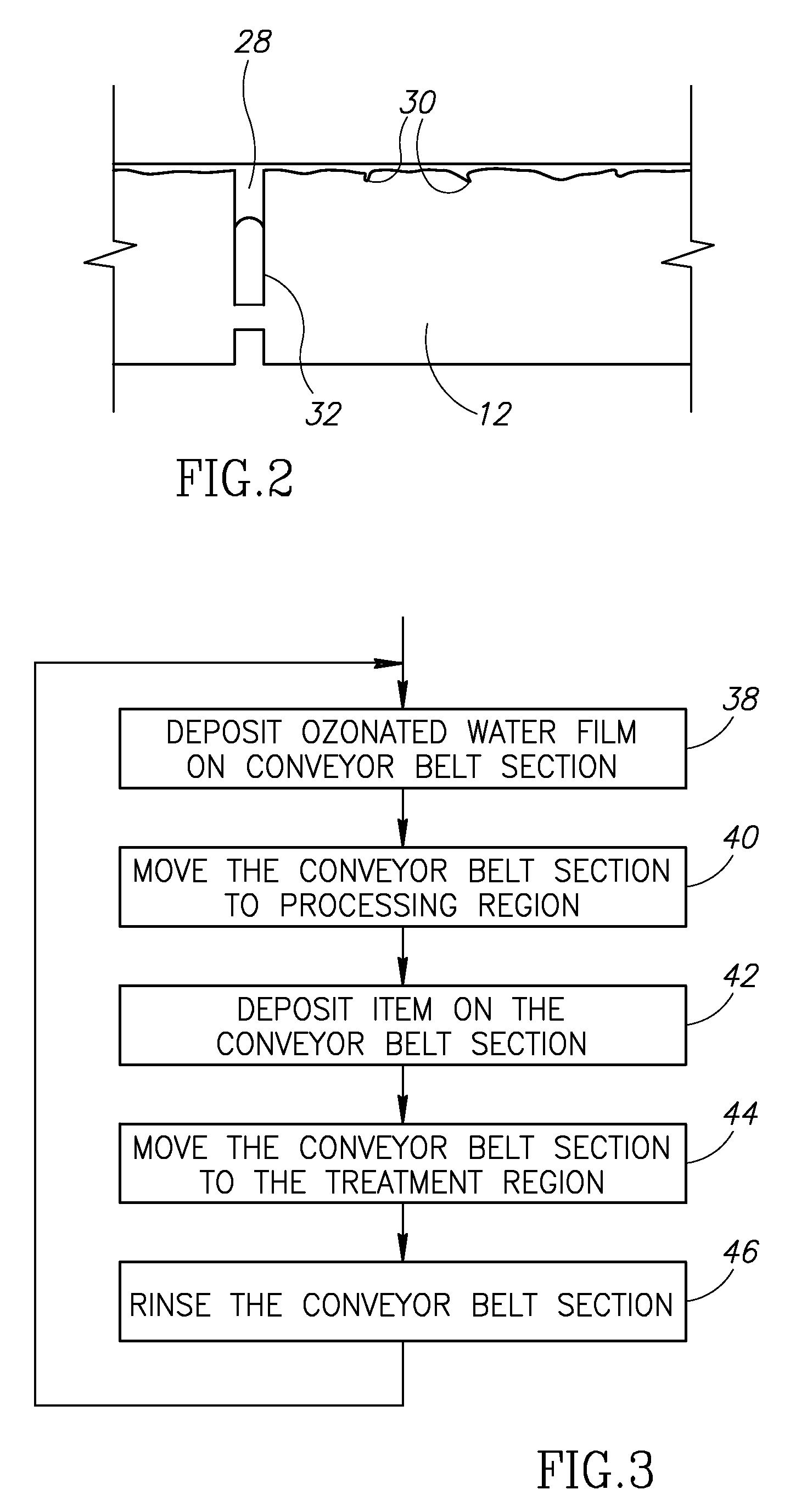
[0013]Referring to FIG. 1, a conveyor treating system 10 includes a conveyor belt 12 and a distributor 14. The conveyor belt 12 travels in direction 16 from a treating region 18 to a processing region 20. A distributor 14 located proximate the treating region 18 deposits a layer of ozonated water on the conveyor belt 12. In the processing region 20, animal carcasses 22, and other meat products are deposited on the conveyor belt 12.

[0014]The distributor 14 may be embodied as a sprayer 24 having multiple heads 26 for spraying ozonated water across substantially the entire width of the conveyor belt 12. In the illustrated embodiment, the sprayer 24 includes heads 26 emitting a jet of water from 10 to 110 degrees wide at a rate of from 0.25 to 5 gallons per minute (gpm). The spray patterns of the heads 26 may overlap to ensure complete coverage. The heads 26 are typically located from 2 to 12 inches from the surface of the conveyor belt 12.

[0015]The ozonated water used typically has a t...


PUM


Abstract

A conveyor cleaning system includes a treating region, a processing region, and a conveyor belt traveling from the treating region to the processing region. A distributor positioned across the treating region deposits a film of ozonated water on the conveyor belt. In the processing region, the conveyor belt is exposed to soiling agents such as grease and other animal matter. A high-pressure rinser may be positioned over the treating section such that the distributor is positioned between the high-pressure rinser and the processing region. Ozonated water may be generated by a system including first and second tanks. The first tank is filled with ozone gas and water. After a predetermined time, undissolved ozone gas is released. The contents of the first tank are then transferred to a second tank along with more ozone gas. After waiting a predetermined time period, undissolved ozone gas is released from the second tank.

Description

FIELD OF THE INVENTION[0001]This invention relates generally to conveyor belts and, more specifically, to cleaning systems for conveyor belts.BACKGROUND OF THE INVENTION[0002]Meat processing factories must be kept extremely clean in order to ensure a safe, clean final product. The United States Department of Agriculture (USDA) strictly enforces regulations requiring meat-processing facilities to maintain proper cleanliness. On-site inspectors will often verify compliance by evaluating both the presence of microbes and the aesthetic appearance of a plant.[0003]In the typical prior plant, conveyor belts and tools are cleaned periodically. In such plants, the entire plant is often shut down in order to thoroughly clean. However, in the periods between cleanings, grease and other soiling materials are allowed to collect and become compacted on the equipment, particularly in recesses, such as surface scratches and the joints between members forming the equipment. This collection of soil ...

Claims


Application Information

Patent Timeline
IPC IPC(8): A22C25/08
CPCA22B5/0082B65G45/22A61L2/22B65G2201/0202
Inventor BRANDT, JIMBRANDT, JONATHAN
Owner OZONE INT
Why Eureka
Try Eureka