High efficiency UV curing system

Inactive Publication Date: 2006-11-09
APPLIED MATERIALS INC
View PDF73 Cites 157 Cited by
  • Summary
  • Abstract
  • Description
  • Claims
  • Application Information

AI Technical Summary

Benefits of technology

[0010] The UV bulbs can be an array of light emitting diodes or bulbs utilizing any of the state of the art UV illumination sources including but not limited to microwave arcs, radio frequency filament (capacitively coupled plasma) and inductively coupled plasma (ICP) lamps. Additionally, the UV light can be pulsed during a cure process.

Problems solved by technology

The moisture is not part of stable films, and can later ca

Method used


Image

  • High efficiency UV curing system
  • High efficiency UV curing system
  • High efficiency UV curing system

Examples


example 1

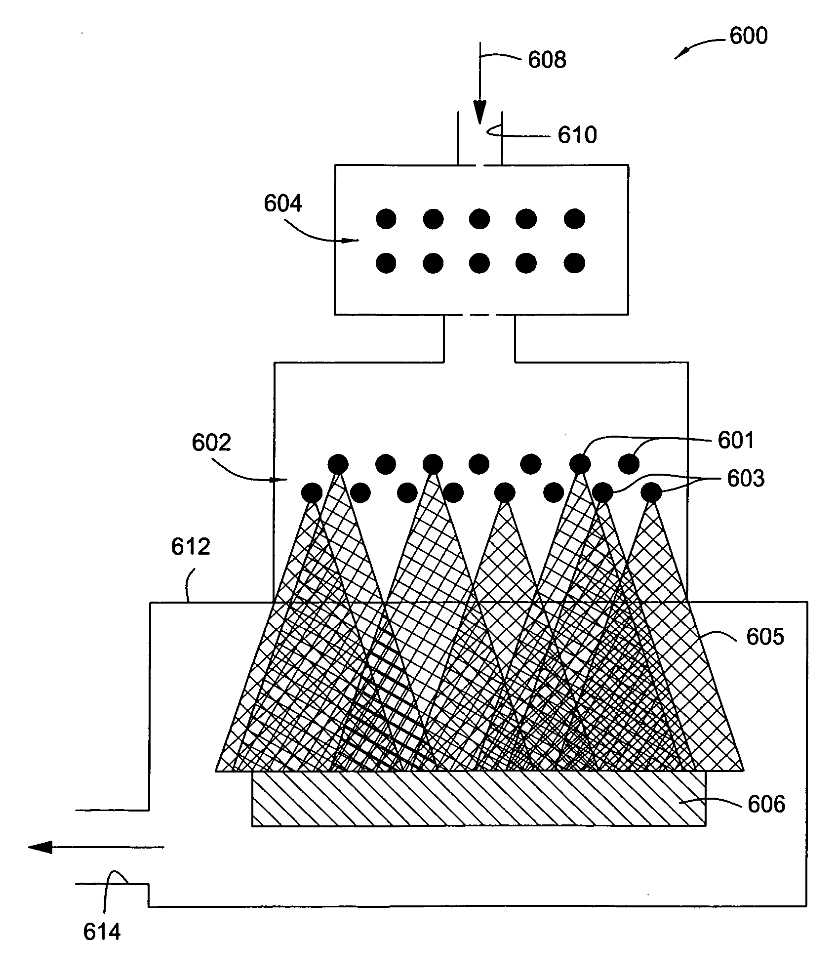
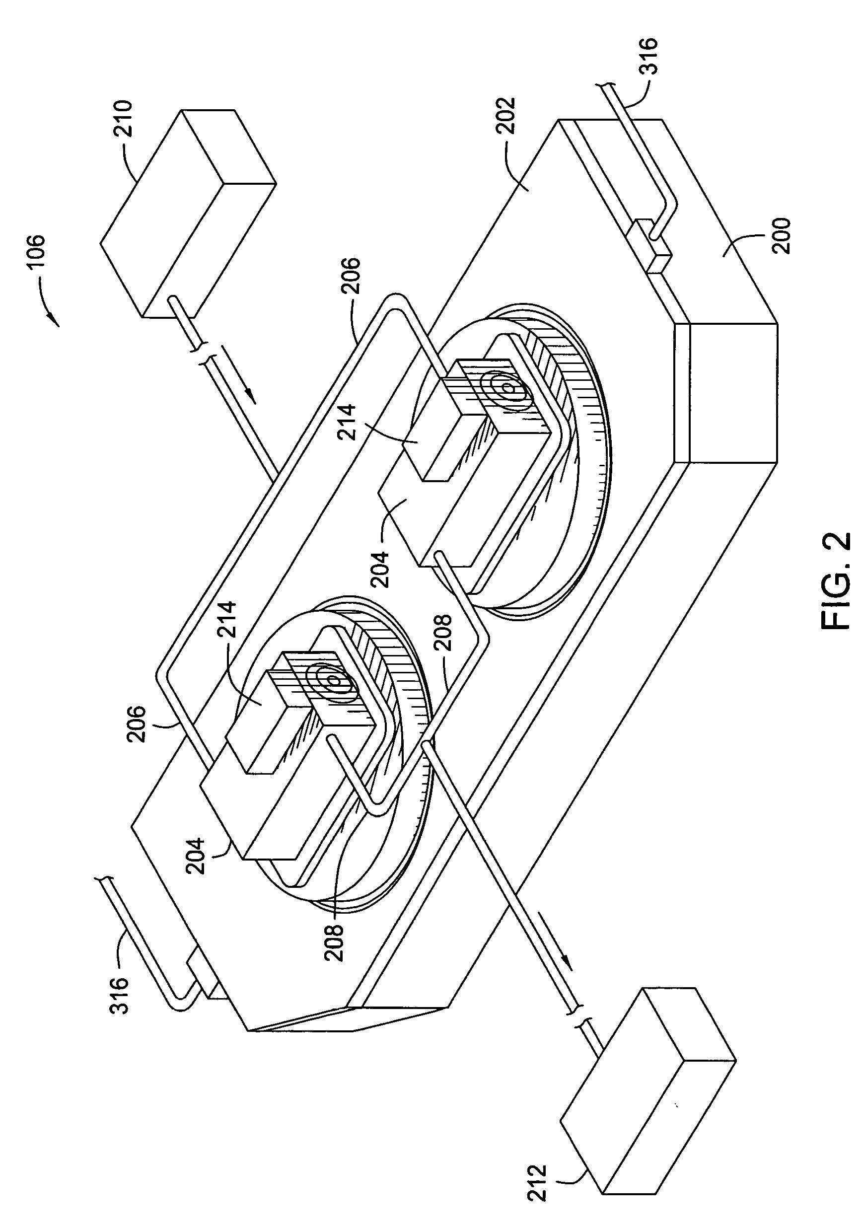
[0032] A cure process for a carbon doped silicon oxide film includes introduction of fourteen standard liters per minute (slm) of helium (He) at eight Torr for the tandem chamber 106 (7 slm per side of the twin) via each inlet passage 316. For some embodiments, the cure processes use nitrogen (N2) or argon (Ar) instead or as mixtures with He since primary concern is absence of oxygen unless other components are desired for reactive UV surface treatments. The purge gas essentially performs two main functions of removing curing byproducts and promoting uniform heat transfer across the substrate. These non-reactive purge gases minimize residue build up on the surfaces within the processing regions 300.

[0033] Additionally, hydrogen can be added to beneficially remove some methyl groups from films on the substrates 300 and also scavenge oxygen which is released during curing and tends to remove too many methyl groups. The hydrogen can getter residual oxygen remaining in the chamber afte...

example 2

[0037] For one embodiment, a clean process includes introduction of 5 slm of ozone and oxygen (13 wt % ozone in oxygen) into the tandem chamber, split evenly within each processing region 300 to generate sufficient oxygen radicals to clean deposits from surfaces within the processing regions 300. The O3 molecules can also attack various organic residues. The remaining O2 molecules do not remove the hydrocarbon deposits on the surfaces within the processing regions 300. A sufficient cleaning can occur with a twenty minute clean process at 8 Torr after curing six pairs of substrates.

[0038]FIG. 4 illustrates a partial section view of a lid assembly 402 with a UV bulb having a long axis 403 oriented vertically above a process region 400. The shape of the reflector in this embodiment is different than in any of the other embodiments. In other words, the reflector geometry must be optimized to ensure maximum intensity and uniformity of illumination of the substrate plane for each lamp sh...


PUM

PropertyMeasurementUnit
Temperatureaaaaaaaaaa

Abstract

An ultraviolet (UV) cure chamber enables curing a dielectric material disposed on a substrate and in situ cleaning thereof. A tandem process chamber provides two separate and adjacent process regions defined by a body covered with a lid having windows aligned respectively above each process region. One or more UV bulbs per process region that are covered by housings coupled to the lid emit UV light directed through the windows onto substrates located within the process regions. The UV bulbs can be an array of light emitting diodes or bulbs utilizing a source such as microwave or radio frequency. The UV light can be pulsed during a cure process. Using oxygen radical/ozone generated remotely and/or in-situ accomplishes cleaning of the chamber. Use of lamp arrays, relative motion of the substrate and lamp head, and real-time modification of lamp reflector shape and/or position can enhance uniformity of substrate illumination.

Description

CROSS REFERENCE TO RELATED APPLICATIONS [0001] This application is a continuation of co-pending U.S. patent application Ser. No. 11 / 124,908, filed May 9, 2005, which is herein incorporated by reference in its entirety.BACKGROUND OF THE INVENTION [0002] 1. Field of the Invention [0003] Embodiments of the invention generally relate to an ultraviolet (UV) cure chamber. More particularly, embodiments of the invention relate to a tandem UV chamber for performing cure processes of dielectric films on substrates and clean processes of surfaces within the tandem chamber. [0004] 2. Description of the Related Art [0005] Silicon oxide (SiO), silicon carbide (SiC) and carbon doped silicon oxide (SiOC) find extremely widespread use in the fabrication of semiconductor devices. One approach for forming silicon containing films on a semiconductor substrate is through the process of chemical vapor deposition (CVD) within a chamber. Organosilicon supplying materials are often utilized during CVD of t...

Claims


Application Information

Patent Timeline
IPC IPC(8): B08B3/12B08B7/00B08B9/00H01L21/306
CPCC23C16/4405B08B7/0035B08B7/00C23C16/401C23C16/44H01L21/205H01L21/304H01L21/67207
Inventor NOWAK, THOMASROCHA-ALVAREZ, JUAN CARLOSKASZUBA, ANDRZEJHENDRICKSON, SCOTT A.HO, DUSTIN W.BALUJA, SANJEEVCHO, TOMCHANG, JOSEPHINEM'SAAD, HICHEM
Owner APPLIED MATERIALS INC
Why Eureka
Try Eureka