Stabilizer circuit for high-voltage discharge lamp

a technology of stabilizer circuit and high-voltage discharge lamp, which is applied in the direction of instruments, process and machine control, light sources, etc., can solve the problems of electromagnetic interference with peripheral devices, electric shock accident, and large weight of lamps, and achieve the effect of reducing consumption power and high consumption power environmen

Inactive Publication Date: 2007-10-02
MEDIATECH INC
View PDF6 Cites 7 Cited by
  • Summary
  • Abstract
  • Description
  • Claims
  • Application Information

AI Technical Summary

Benefits of technology

[0014]Therefore, the present invention is directed to provide a stabilizer circuit for a high-voltage discharge apparatus, which is available in a high consumption power environment and is capable of reducing consumption power.

Problems solved by technology

In addition, the lamp has great weight and volume, which makes it difficult to dispose and treat.
All such stabilizers, however, may cause electromagnetic interference with peripheral devices or electric shock accident.
The conventional stabilizer circuit for the high-voltage discharge lamp described above is available in capacity of 70 to 140 W. However, in high capacity exceeding for example 250 W, current increases, damaging the voltage control logic IC2 of the buck converter 10.

Method used


Image

  • Stabilizer circuit for high-voltage discharge lamp
  • Stabilizer circuit for high-voltage discharge lamp
  • Stabilizer circuit for high-voltage discharge lamp

Examples


Embodiment Construction

[0025]The present invention will now be described with reference to the accompanying drawings, in which preferred embodiments of the invention are shown. However, the invention should not be construed as limited to only the embodiments set forth herein. Rather, these embodiments are presented as teaching examples.

[0026]Numerous specific details are set forth to provide a thorough description of various embodiments of the invention. Certain embodiments of the invention may be practiced without these specific details or with some variations in detail. In some instances, certain features are described in less detail so as not to obscure other aspects of the invention. The level of detail associated with each of the elements or features should not be construed to qualify the novelty or importance of one feature over the others.

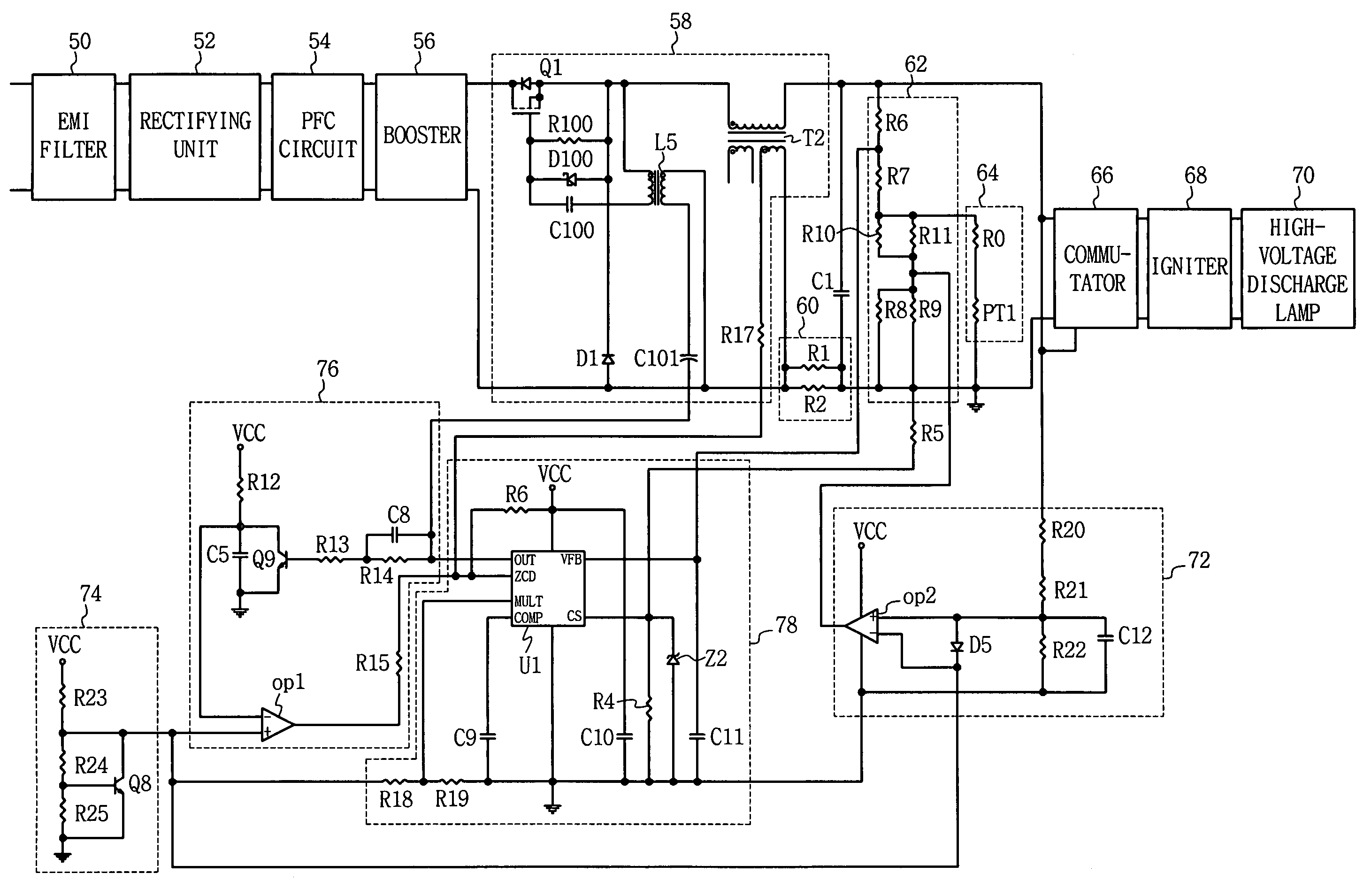
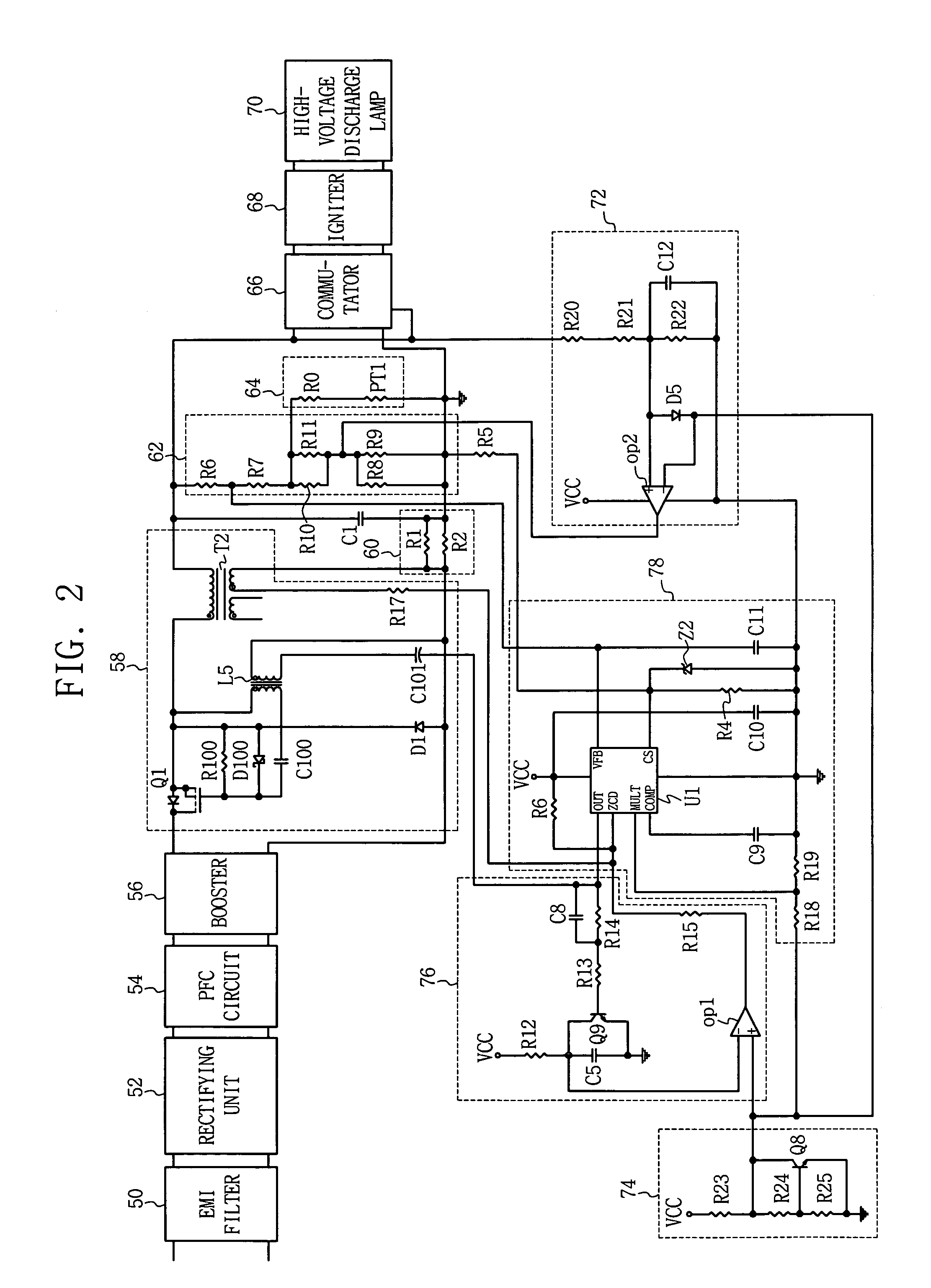
[0027]Referring to FIG. 2, a stabilizer for a high-voltage discharge apparatus according to an embodiment of the present invention comprises an electromagnetic in...


PUM


Abstract

A stabilizer circuit for a high-voltage discharge lamp is provided. The stabilizer comprises an electromagnetic interference (EMI) filter; a rectifying unit; a power factor correction (PFC) circuit; a buck converter; a commutator; an igniter; a high-voltage discharge lamp; a current detector; a voltage detector; an igniter voltage controller for receiving the voltage output from the igniter and controlling the voltage when abnormality in the high-voltage discharge lamp occurs.

Description

CROSS-REFERENCE TO RELATED APPLICATIONS[0001]Pursuant to 35 U.S.C. § 119, this application claims the benefit of earlier filing date and right of priority to Korean Patent Application No. 10-2004-113743, filed Dec. 28, 2004, the content of which is hereby incorporated by reference herein in its entirety.COPYRIGHT & TRADEMARK NOTICES[0002]A portion of the disclosure of this patent document contains material, which is subject to copyright protection. The owner has no objection to the facsimile reproduction by any one of the patent document or the patent disclosure, as it appears in the Patent and Trademark Office patent file or records, but otherwise reserves all copyrights whatsoever.[0003]Certain marks referenced herein may be common law or registered trademarks of third parties affiliated or unaffiliated with the applicant or the assignee. Use of these marks is for providing an enabling disclosure by way of example and shall not be construed to limit the scope of this invention to ...

Claims


Application Information

Patent Timeline
Patent Type & Authority Patents(United States)
IPC IPC(8): G05F1/00
CPCH05B41/288Y10S315/04Y10S315/05H05B41/16H05B41/231
Inventor KIM, BYUNG-SUNSEOK, KYUNG-SOO
Owner MEDIATECH INC
Why Eureka
Try Eureka