Magnetic resonance imaging system

a magnetic resonance imaging and magnetic resonance technology, applied in the field of magnetic resonance imaging system, can solve the problems of time-consuming adjustment of the posture of the magnet using a special tool, hindering the adjustment work, vibration may adversely affect the image resulting from magnetic resonance imaging, etc., to achieve suppress the adverse effect of images and easy adjustment of the posture of the magn

Inactive Publication Date: 2007-10-02
GE MEDICAL SYST GLOBAL TECH CO LLC
View PDF13 Cites 27 Cited by
  • Summary
  • Abstract
  • Description
  • Claims
  • Application Information

AI Technical Summary

Benefits of technology

[0013]According to the present invention, there is provided a magnetic resonance imaging system in which the posture of a magnet can be easily adjusted, and the adverse effect on images can be suppressed.

Problems solved by technology

However, it is time-consuming to adjust the posture of the magnet using a special tool such as the jack.
This hinders the adjustment work.
Furthermore, when the adjustment sheet is merely sandwiched between the floor and the leg, the vibration of the floor is propagated to the magnet through the portion of the placement surface of the floor under the leg.
The vibration may adversely affect images resulting from magnetic resonance imaging.

Method used


Image

  • Magnetic resonance imaging system
  • Magnetic resonance imaging system
  • Magnetic resonance imaging system

Examples


Embodiment Construction

[0022]Referring to the appended drawings, an embodiment of the present invention will be described below.

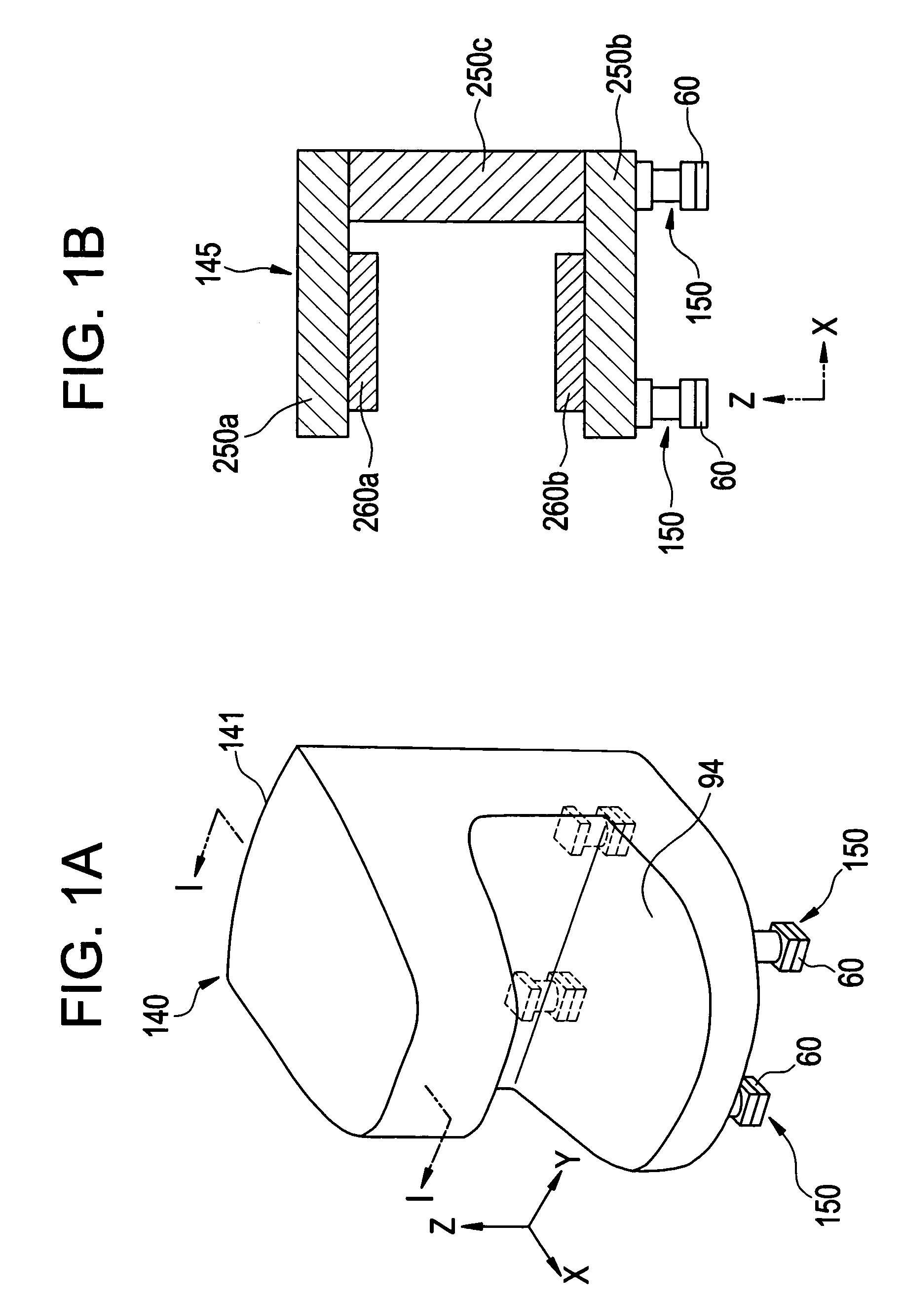
[0023]FIG. 1(a), FIG. 1(b), and FIG. 2 show the major parts of an MRI system in accordance with an embodiment of the present invention, and the appearance of the MRI system.

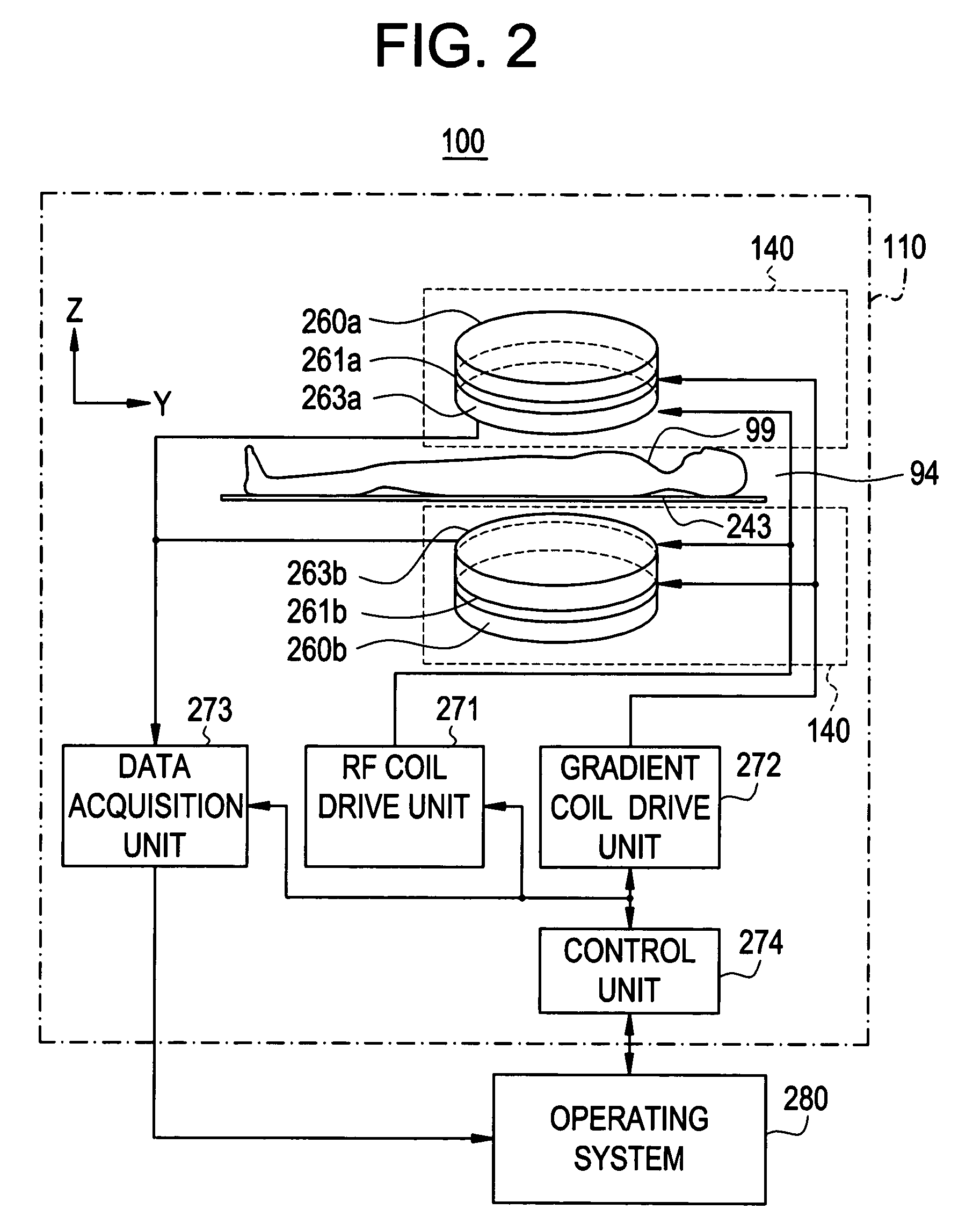
[0024]As shown in FIG. 1(a), FIG. 1(b), and FIG. 2, an MRI system 100 in accordance with the present embodiment comprises an MRI system body 110 and an operating system 280.

[0025]The MRI system body 110 comprises a magnet system 140, an RF coil drive unit 271, a gradient coil drive unit 272, a data acquisition unit 273, and a control unit 274.

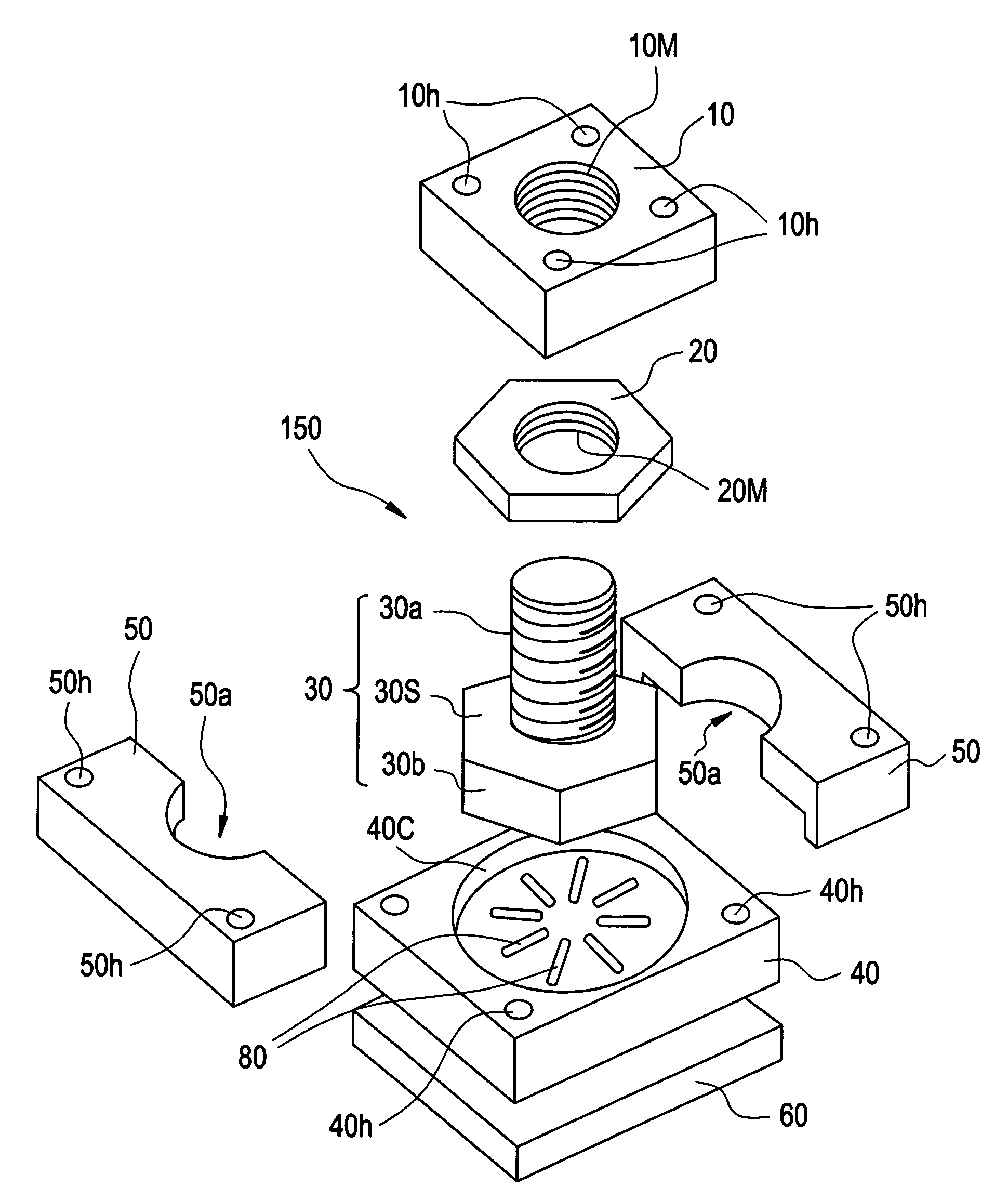
[0026]FIG. 1(a) is a perspective view of the magnet system 140. As shown in FIG. 1(a), the magnet system 140 includes a housing 141 and legs 150.

[0027]The legs 150 serve as a concrete example of the supporting means included in the present invention.

[0028]A magnet 145 is accommodated in the housing 141. FIG. 1(b) is a sectional view of the magnet 145 seen in an I-I direct...


PUM


Abstract

Provided is a magnetic resonance imaging system in which the posture of a magnet can be easily adjusted and the adverse effect on images can be suppressed. The magnetic resonance imaging system comprises a magnet that induces a static magnetic field, and legs that support the magnet and stand on a placement surface. The leg includes a posture adjustment mechanism that adjusts the posture of the magnet and an attenuation pad that attenuates a vibration applied through the placement surface into a vibration whose frequency is different from the resonant frequency of the magnet.

Description

CROSS REFERENCE TO RELATED APPLICATIONS[0001]This application claims the benefit of Japanese Application No. 2003-060963 filed Mar. 7, 2003.BACKGROUND OF THE INVENTION[0002]The present invention relates to a magnetic resonance imaging system utilizing magnetic resonance.[0003]As described in, for example, Japanese Unexamined Patent Application Publication No. 2002-159465, a magnetic resonance imaging (MRI) system is a modality for imaging a region to be examined of a subject lying down in a static magnetic field space by utilizing magnetic resonance.[0004]A magnet such as a permanent magnet is used to induce a static magnetic field. The magnet is borne by legs that are used to adjust the posture of the magnet and disposed on the floor in an installation site of an MRI system. For example, when the magnet is disposed in the installation site or if a gap is created between the floor and any of the legs because the floor has deformed time-sequentially, the posture of the magnet must be...

Claims


Application Information

Patent Timeline
Patent Type & Authority Patents(United States)
IPC IPC(8): G01V3/00G01R33/383A61B5/055G01R33/38
CPCG01R33/3806G01R33/3802E21D20/028E21D21/0026E21D21/0093
Inventor KITAGAWA, SEIICHISATO, TAKAMI
Owner GE MEDICAL SYST GLOBAL TECH CO LLC
Why Eureka
Try Eureka