
Radial-hinge mechanism

a radial hinge and mechanism technology, applied in the direction of folding chairs, branching pipes, light support devices, etc., can solve the problems of radial hinge movement, and achieve the effect of superior radial pivoting motion and enhanced mechanism usefulness

Active Publication Date: 2007-10-09
ROUSE GLENN R
View PDF16 Cites 14 Cited by
  • Summary
  • Abstract
  • Description
  • Claims
  • Application Information

AI Technical Summary

Benefits of technology

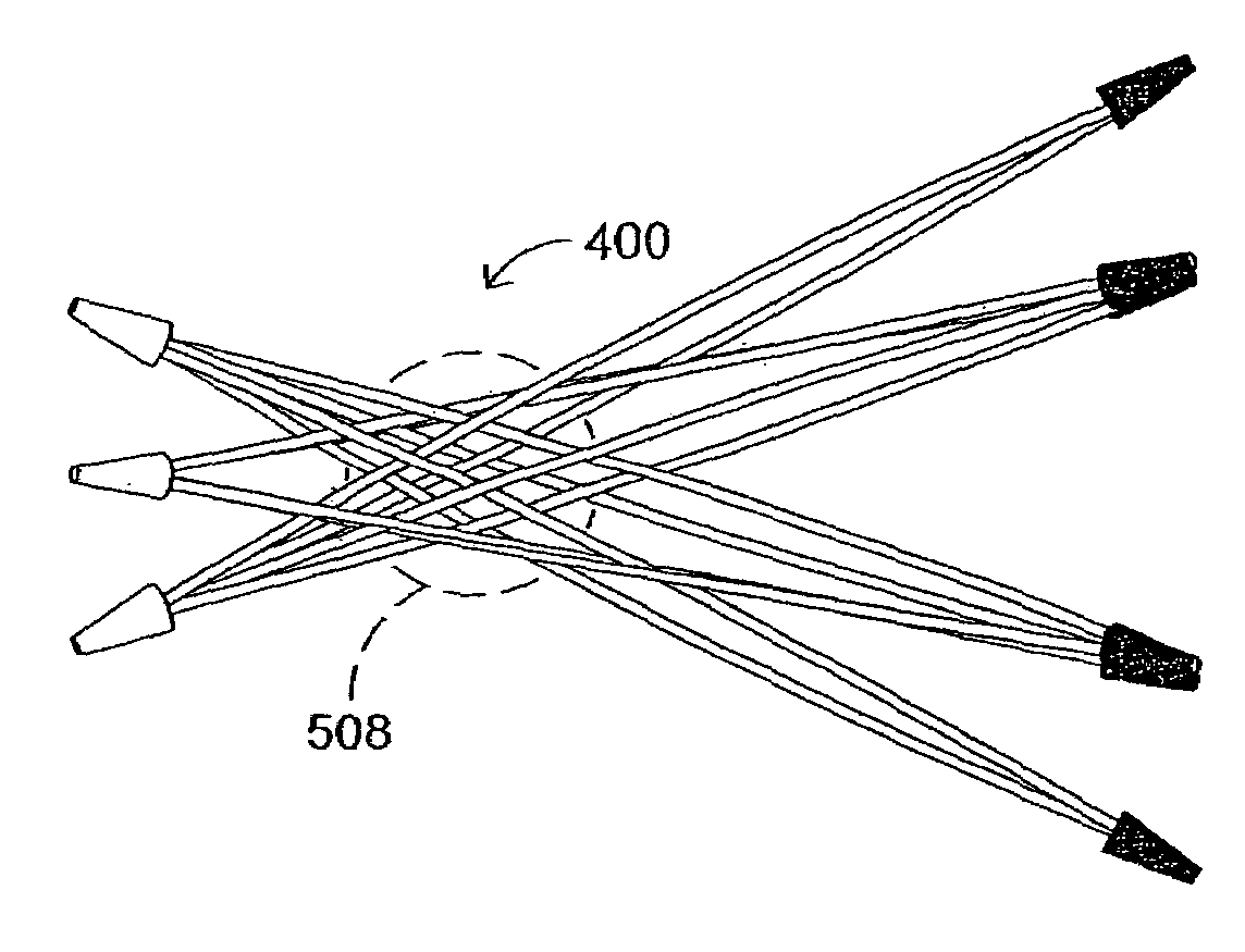
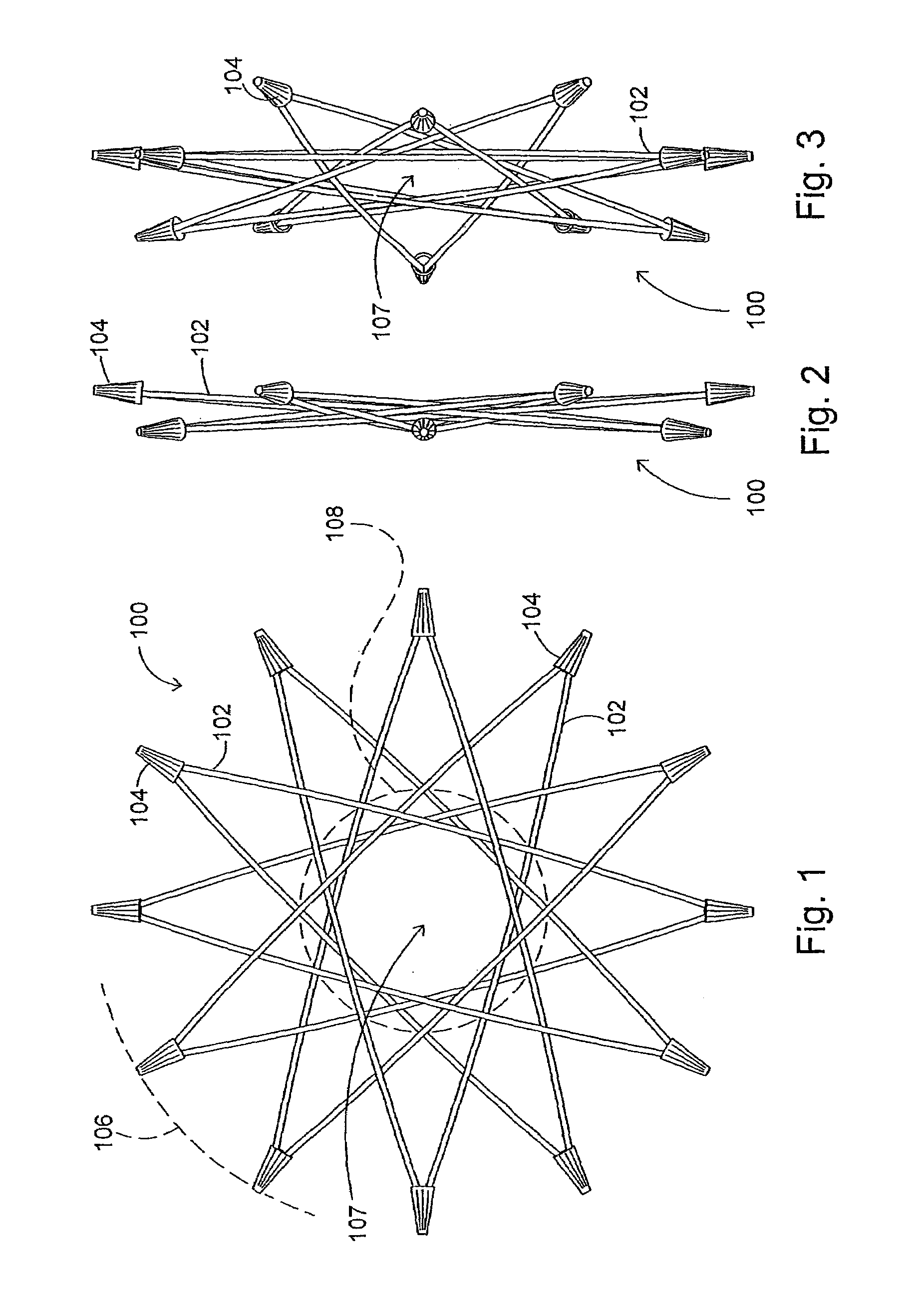
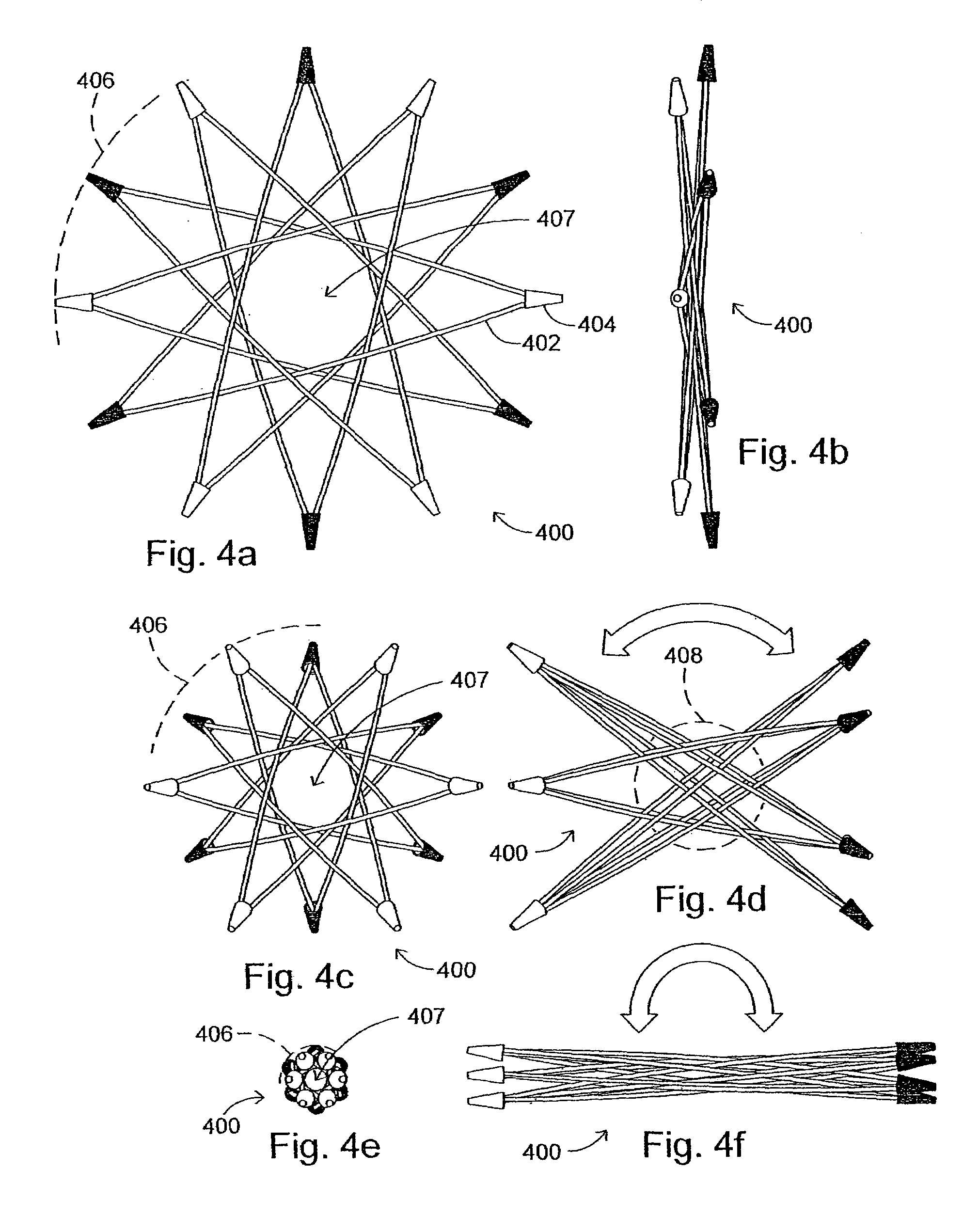
"The present invention is a radial-hinge mechanism that is designed to naturally pivot open and close upon a centrally-located hinge-core. The mechanism is made up of elongated members that are interconnected around a circular inner-aperture. The design-parameters apply to a vast family of radial-hinge mechanisms that all have an even number of crossmembers of eight or more. The mechanism provides a versatile solution for a variety of applications and can be used alone or in conjunction with other mechanisms. It can also be used in a stacked configuration with other radial-hinge mechanisms. The mechanism can interface with encasements, bellows, propellers, blades, fins, shafts, and other similar components. Overall, the invention offers a unique and effective solution for achieving radial pivoting motion without the need for curved or coiled members."

Problems solved by technology

However, these devices do not join the ends of one beam with an end of another beam, nor are any of these designs and devices based on one continuous interweaving loop of elongated elements.
While the above-described patents disclose beams (also called out as struts, rods, sticks, tubes, members and elements), which may be utilized in conjunction with each other to form various structures, these structures are not capable of radial-hinge movement nor do their completed forms result in unitized continuous-loop frameworks that evenly distribute loads, transfer forces, and assist or resist with various spring-action potentials.

Method used


Image

  • Radial-hinge mechanism
  • Radial-hinge mechanism
  • Radial-hinge mechanism

Examples


Embodiment Construction

)

[0080]The present invention is directed to a radial-hinge mechanism comprised of one or more elongated members arranged, formed and interconnected around a substantially circular inner-aperture into a specific closed-loop assembly which unitizes the mechanism's structure and actualizes its potential to perform similar to a scissor-hinge. Furthermore, this mechanism includes a hinge-core that can move or be translocated laterally within the framework, with crossmembers radiating out tangentially from the inner-aperture. In addition, this closed-loop assembly is based on unique geometric design-parameters, which also apply to a vast family of radial-hinge mechanisms, ranging in spoke-count from eight to infinity on the even-number scale. However, it should be appreciated that when the number of the spokes of the radial-hinge mechanism exceed a certain higher enumeration, the mechanism may not be capable of realistic implementation due to material and dimensional limitations.

[0081]Wit...


PUM


Abstract

A radial-hinge mechanism includes one or more elongated members arranged and interconnected into a unique, geometry-based, closed-loop assembly often resembling a multi-point star when in its fully-closed mode. The mechanism's signature function is its variable nature of pivoting open from a centralized hinge-core as its substantially circular inner-aperture concurrently contracts in its own circular dimensions. Additionally, the mechanism has a natural susceptibility to spring-biasing techniques to further modify its versatility and performance. Applications for the mechanism include numerous support frameworks along with devices and apparatus encompassing the likes of: sheaves and spools; weight-scales and elevators; shock and impact absorbers; throwers and grabbers; interfaces with bellows for valves and pumps; interfaces with fans, props and cutters; interfaces with shafts for functions of braking, clutching, gripping; and a stacking of radial-hinge mechanisms or casting in arrays; in addition to combinations of forms and attachments applicable to the mechanism's multi-functional propensities.

Description

BACKGROUND OF THE INVENTION[0001]The present invention is directed to a radial-hinge mechanism and, more specifically, a radial-hinge mechanism that includes a plurality of elongated interwoven elements.[0002]A variety of prior art devices have utilized elongated elements to form a structure. For example, U.S. Pat. No. 4,731,962 discloses a compression-tension unit for use in a tensile-integrity structure or in combination with similar compression-tension units in such a structure. This compression-tension unit includes elongated rigid struts of circular cross-section that each include slotted ends which receive a portion of an elastic cord to connect one strut to another.[0003]As another example, U.S. Pat. No. 3,546,049 discloses a device that includes a plurality of beams formed from sets of elongated elements. In one embodiment, the device includes four beams, each including two elements symmetrically arrayed about a geometric center or axis of the beam. These beams contact at a ...

Claims


Application Information

Patent Timeline
Patent Type & Authority Patents(United States)
IPC IPC(8): E04B1/19A47B3/00A47C4/00E04B1/343E04C3/00A47C4/42E04B1/32E04B1/344E04H15/48E04H15/50F16M11/38F21V21/06
CPCA47B3/002A47C4/42E04B1/3211E04B1/3441E04H15/48E04H15/50F16M11/38F16M11/043F16M11/121A47C4/286Y10T403/45F21V21/06F16M2200/065F16M2200/04Y10T403/342Y10T403/347
Inventor ROUSE, GLENN R.
Owner ROUSE GLENN R
Learn More