
Window candle holder

a window candle and holder technology, applied in the field of window candles, can solve the problems of undue stress, difficulty in adequately supporting them in a consistent upright manner on even the most common/standard window sill, etc., and achieve the effect of preventing impeded normal operation of the window and being easy to attach to the window sill

Inactive Publication Date: 2007-10-09
COOPER JAMES +2
View PDF7 Cites 15 Cited by
  • Summary
  • Abstract
  • Description
  • Claims
  • Application Information

AI Technical Summary

Benefits of technology

"The invention is a device that allows a window candle to be supported on a window frame for easy access from the outside. The device includes a window frame, a U-shaped base with a retaining cavity for the candle, and a clip for attachment to the window frame. The base is securely positioned using the clip, which is attached to the window frame. The device is easy to install and does not interfere with the normal operation of the window. The technical effect of the invention is a more stable and universal method of maintaining window candles in a consistent fashion within the window view."

Problems solved by technology

Due in part to the awkward cords for electric window candles, a common problem with displaying candles in windows is that it is difficult to adequately support them in a consistent upright manner on even the most common / standard window sill.
Prior attempts to secure candles to window sills include the use of adhesive tape, thumb tacks, and even stapling said electric cord to the window sill—all ineffective attempts to solving the problem as these methods typically cause damage to the window sill, as well as providing undue stress during the already hectic holiday season.

Method used


Image

  • Window candle holder
  • Window candle holder
  • Window candle holder

Examples


Embodiment Construction

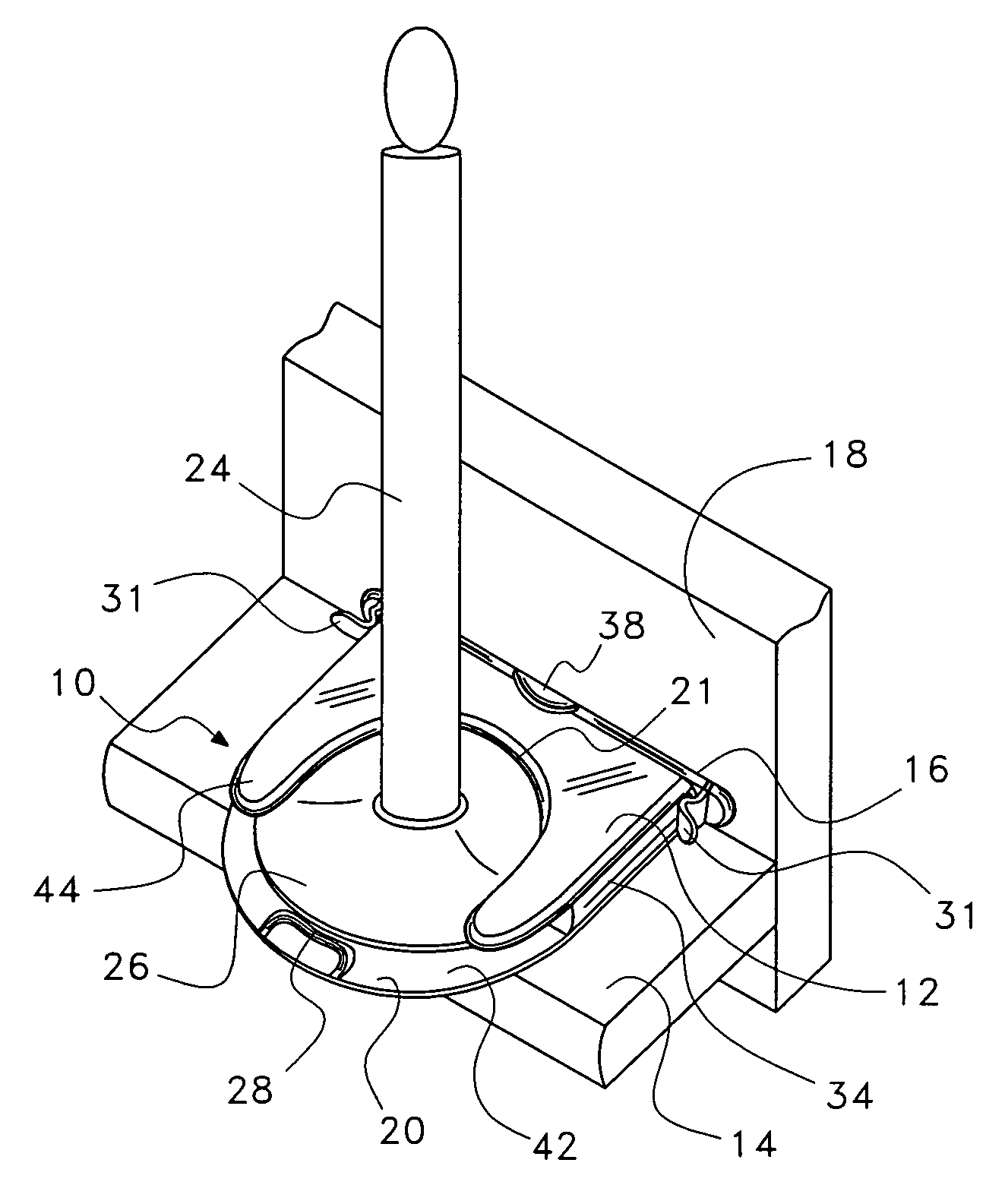
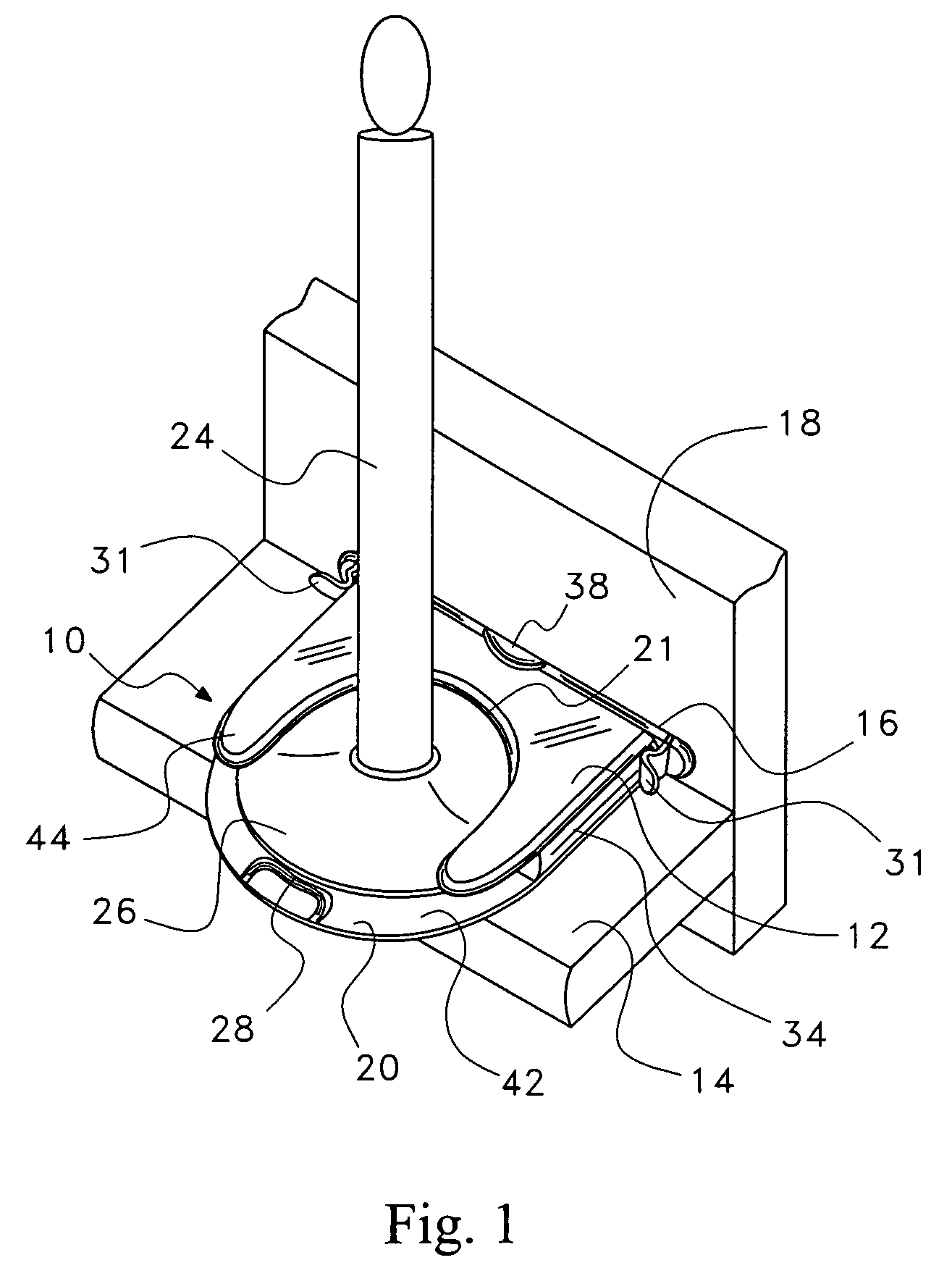
[0018]Referring now to the drawings in detail wherein like reference numerals have been used throughout the various figures to designate like elements, there is shown in FIG. 1 a perspective view of the window candle holder constructed in accordance with the general principles of the invention and designated generally as 10. The window candle holder 10 is comprised of a support base 12 that rests on or is attached to window sill 14, and a mounting clip 16. The mounting clip 16 being attached to a window sash 18 interacts with the support base 12 securing the holder 10 to both the window sill 14 and window sash 18.

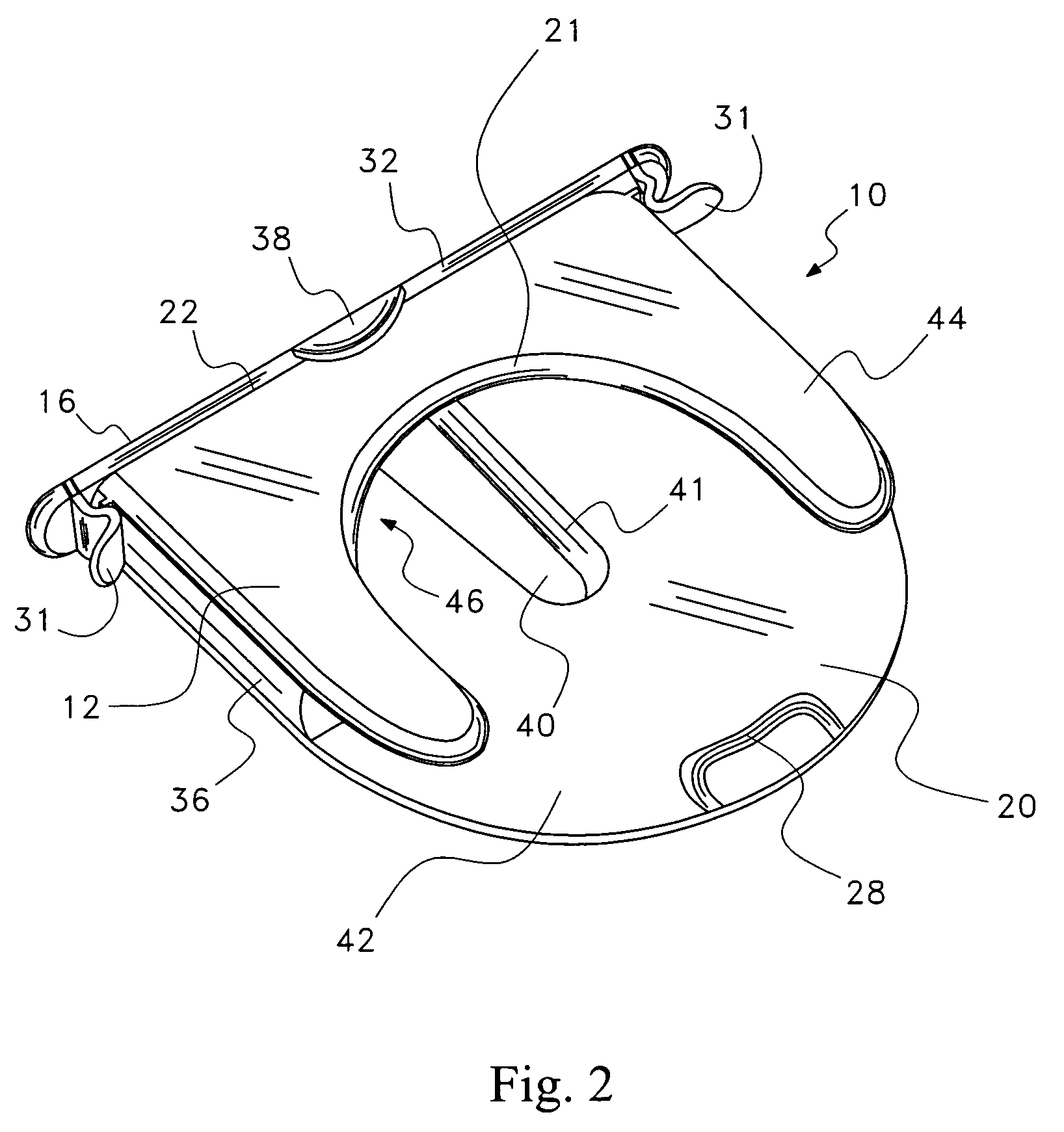
[0019]In the preferred embodiment, the window candle holder 10 is preferably constructed from plastic, wood or metal. While installed, the base 12 extends in a horizontal plane. The support base 12 is comprised of a candle end 20 and a contact end 22. The candle end 20 provides the means for attaching a window candle 24. The candle end 20 is preferably substantially circula...


PUM


Abstract

A holding device for supporting electric or battery-operated window candles in an upright vertical position for viewing through a window. The holding device is comprised of a horizontally extending U-shaped support base, and a vertically extending clip for attaching to a window sash which connects the support base and candle to the window. The support base accommodates a design that holds the candle base in a stationary position while the opposite end abuts the clip and window sash. The clip is attached to the window sash where said sash meets the window sill and extends upwardly. The support base and candle are connected to the window by attaching the back wall of the base to the clip that abuts the window sash. The profile and design does not impede access to normal window functions leaving space between the candle and window handle for grasping.

Description

FIELD OF THE INVENTION[0001]The present invention relates to window candles, and more particularly to a device for supporting window candles in their upright vertical position on a window sill for visual access.BACKGROUND OF THE INVENTION[0002]Window candles are used for their aesthetic appeal at various times of the year; however, they are most commonly used around the winter holidays for decoration. The common method of use for the candles is to place them on window sills for viewing from outside the home. Due in part to the awkward cords for electric window candles, a common problem with displaying candles in windows is that it is difficult to adequately support them in a consistent upright manner on even the most common / standard window sill. An object of this invention is to provide support for candles on various types and sizes of window sills. Prior attempts to secure candles to window sills include the use of adhesive tape, thumb tacks, and even stapling said electric cord to...

Claims


Application Information

Patent Timeline
Patent Type & Authority Patents(United States)
IPC IPC(8): F21V21/00A47F5/00
CPCF21S6/001F21V21/088F21S9/02Y10S362/81F21W2121/004F21W2121/00
Inventor COOPER, JAMESMINIELLY, R. MATTHEWHUNTER, DALE
Owner COOPER JAMES
Learn More