Contrast from rotating frame relaxation by adiabatic pulses

a technology of adiabatic pulses and rotating frames, applied in the field of magnetic resonance spectroscopy, can solve the problems of increasing si, inability to completely rule out, and inadequate current methods for generating contrast in rotating frames

Active Publication Date: 2007-10-09
RGT UNIV OF MINNESOTA
View PDF18 Cites 25 Cited by
  • Summary
  • Abstract
  • Description
  • Claims
  • Application Information

AI Technical Summary

Problems solved by technology

Current methods for assessing relaxation and generating contrast in the rotating frame are inadequate.
Although a small contribution from a positive Nuclear Overhauser Effect (NOE) associated with the fast motional regime can lead to an increase in the SI, it cannot be completely ruled out.
Modeling based on the anisochronous DA mechanism (in the FXL) alone leads to an impossible dependence of δω on magnetic field.

Method used


Image

  • Contrast from rotating frame relaxation by adiabatic pulses
  • Contrast from rotating frame relaxation by adiabatic pulses
  • Contrast from rotating frame relaxation by adiabatic pulses

Examples


example

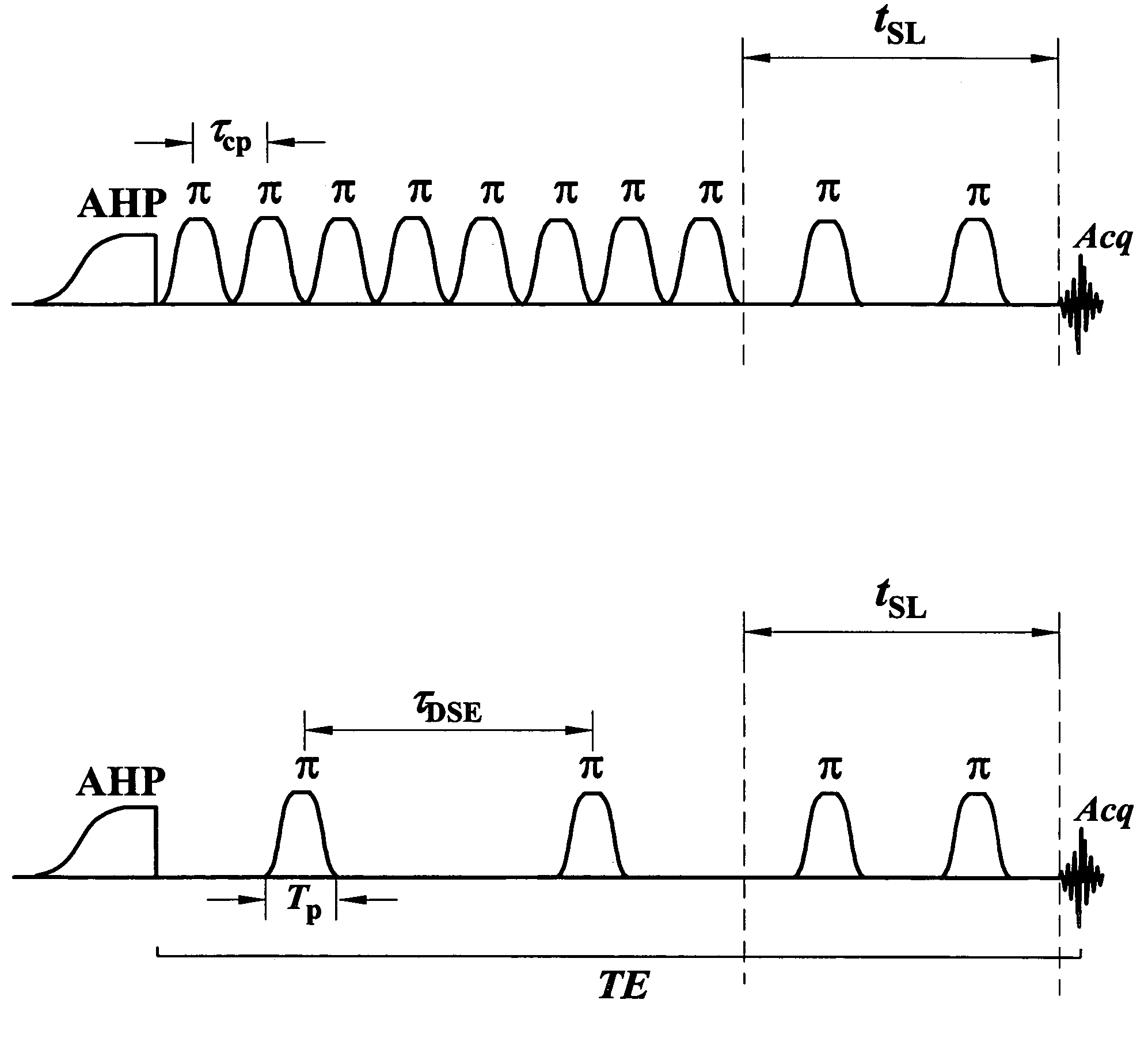
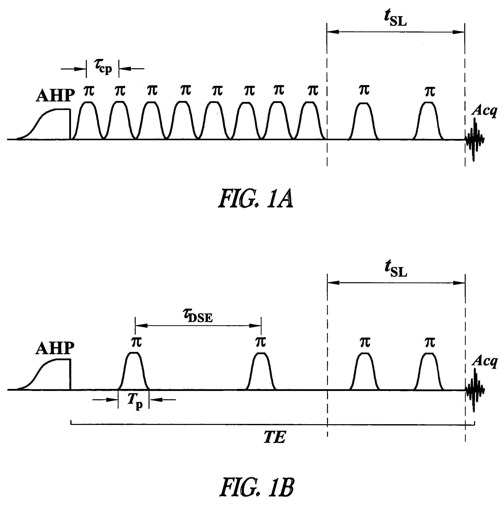
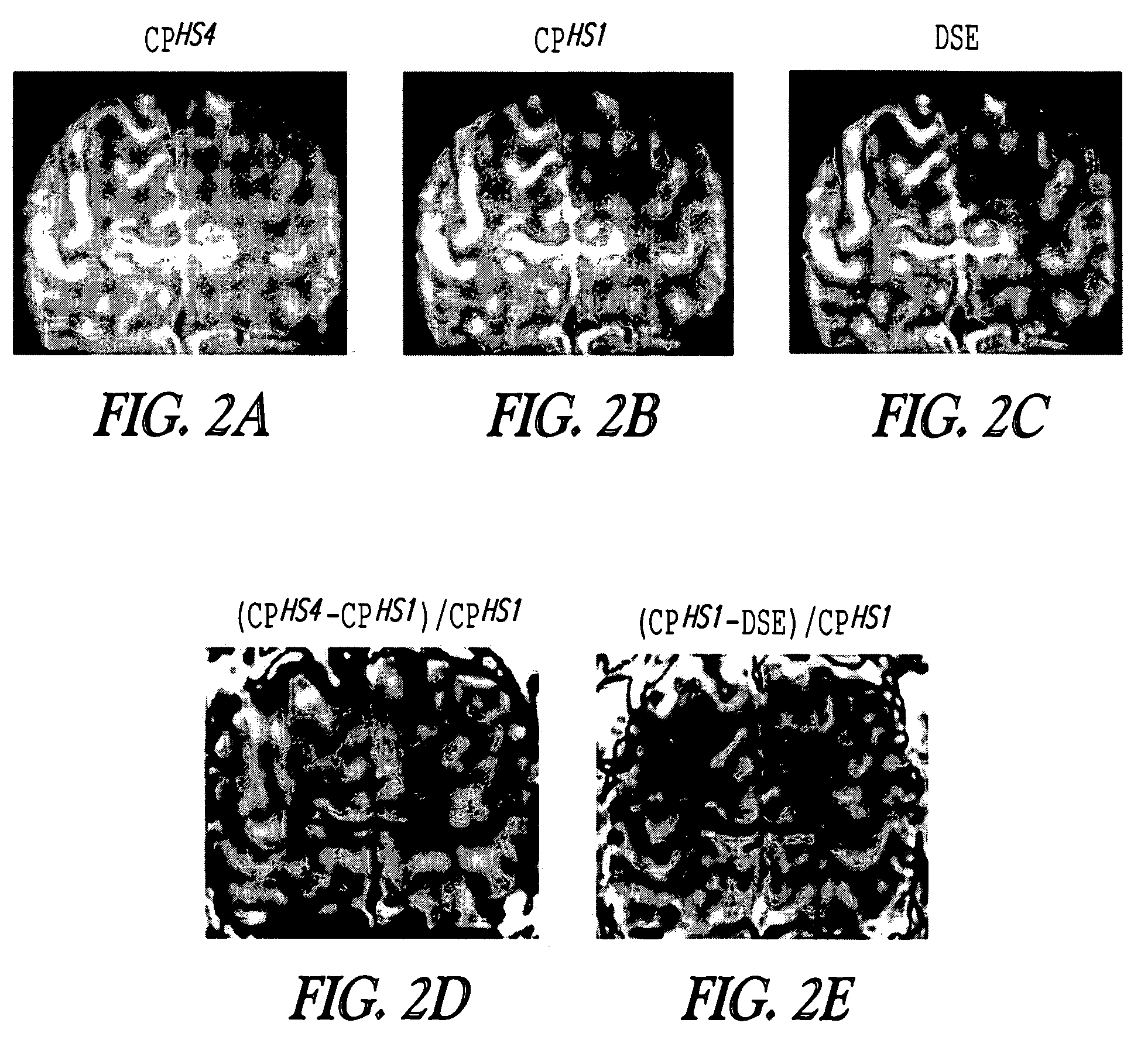
[0054]In one example, MRI studies were performed on healthy volunteers using instruments having Varian Unity INOVA consoles (Varian Associates, CA, USA) interfaced to a 90 cm bore 4T magnet (OMT, Inc., Oxon, UK) and to a 90 cm bore 7T magnet (Magnex Scientific, UK). 1H quadrature surface coils consisting of two geometrically decoupled turns (each 7 cm in diameter) were used for the measurements. T2ρ and T2† images were measured with a segmented spiral readout, using (0.7 mm)2 in-plane resolution, FOV=(18 cm)2, 2562 matrix, 8 segments, acquisition time (AT)=35 ms, and thickness=3 mm. Shimming was performed with a fully adiabatic version of the fast automatic shimming technique by mapping along projections, FASTMAP. Before the excitation pulse in the sequences, the fat signal at 1.3 ppm was suppressed by variable-power RF pulses with optimized relaxation delays, VAPOR. Two dummy scans were used to achieve a steady state prior to data collection.

[0055]T2ρ measurements were performed us...


PUM


Abstract

This document discusses, among other things, a system and method for modulating transverse and longitudinal relaxation time contrast in a rotating frame based on a train of radio frequency pulses.

Description

CROSS-REFERENCE TO RELATED APPLICATIONS[0001]This document claims the benefit of priority, under 35 U.S.C. § 119(e), to Shalom Michaeli et. al, U.S. Provisional Patent Application Ser. No. 60 / 616,257, entitled “TRANSVERSE AND LONGITUDINAL RELAXATION TIME CONTRAST IN THE ROTATING FRAME GENERATED BY ADIABATIC RF PULSES,” filed on Oct. 6, 2004, which is incorporated herein by reference.GOVERNMENT INTEREST[0002]This work was supported by NIH grants CA92004, RR08079, NS 40801, EB 00422, the Keck Foundation, the MIND Institute, the National Foundation for Functional Brain Imaging and the US Department of Energy. The United States government has certain rights in the technology disclosed herein.TECHNICAL FIELD[0003]This document pertains generally to magnetic resonance spectroscopy, and more particularly, but not by way of limitation, to contrast from rotating frame relaxation by adiabatic pulses.BACKGROUND[0004]Relaxation is a measure of the differences in the way that a molecule, such as...

Claims


Application Information

Patent Timeline
Patent Type & Authority Patents(United States)
IPC IPC(8): G01V3/00
CPCG01R33/50G01R33/446
Inventor MICHAELI, SHALOMGARWOOD, MICHAEL G.UGURBIL, KAMILSORCE, DENNIS J.
Owner RGT UNIV OF MINNESOTA
Why Eureka
Try Eureka