Bandwidth optimization of ring topology through propagation delay compensation

a technology of propagation delay compensation and ring topology, applied in the field of ring topology digital networks, to achieve the effect of improving clock synchronization and reducing bandwidth loss

Active Publication Date: 2007-10-09
CIRRUS LOGIC INC
View PDF5 Cites 49 Cited by
  • Summary
  • Abstract
  • Description
  • Claims
  • Application Information

AI Technical Summary

Benefits of technology

[0007]The present inventions provides apparatus and methods for reducing loss of bandwidth due to clock skewing from propagation delay be improved clock synchronization among nodes in a ring topology digital network environment. First, the total ring propagation delay is determined. The master node transmits a clock signal into the network in one direction. Each slave node propagates the signal to the next slave node without regeneration until the signal is received by the master node. The amount of time the signal takes to travel around the ring, based on the signal's time of transmission from the master node and time of arrival at the master node, is measured. The master node then transmits...

Problems solved by technology

However, due to the physical length of each ring segment, a propagation delay occurs in each se...

Method used


Image

  • Bandwidth optimization of ring topology through propagation delay compensation
  • Bandwidth optimization of ring topology through propagation delay compensation
  • Bandwidth optimization of ring topology through propagation delay compensation

Examples


Embodiment Construction

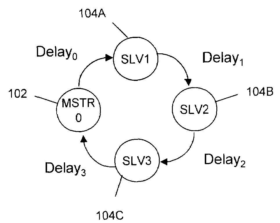
[0018]The process of the present invention will be described with reference to FIGS. 3A-3D and the flow chart of FIG. 4. First, the total ring propagation delay is determined. The master node 102 transmits a clock signal into the network in one direction (FIG. 3A, step 400). Each slave node 104A, 104B and 104C propagates the signal to the next slave node without regeneration (step 402) until the signal is received by the master node 102 (step 404). The amount of time diff0 the signal takes to travel around the ring, based on the signal's time of transmission from the master node 102 and time of arrival at the master node 102, is measured (step 406).

[0019]The master node 102 then transmits a clock signal in both directions to the first slave node 104A (FIG. 3B, step 408). The first slave node 104A receives both signals (step 410) and measures the difference in the two signals' arrival times diff1 (step 412). The process is repeated for each other slave node (FIGS. 3C and 3D, step 414...


PUM


Abstract

In a ring topology digital network propagation delay is reduced A master node transmits a clock signal into the network in one direction. Each slave node propagates the signal to the next slave node without regeneration until the signal is received by the master node. The amount of time the signal takes to travel around the ring, is measured and is the total ring propagation delay. The master node then transmits a clock signal in both directions to the first slave node which measures the difference in their arrival times and transmits the difference to the master node. The process is repeated for each other slave node. Based upon each difference the master node computes the propagation delay for each ring segment. The master node transmits to each slave node the corresponding ring segment propagation delay and each slave node adjusts the phase of the node's clock.

Description

TECHNICAL FIELD[0001]The present invention relates generally to the field of ring topology digital networks and, in particular, to improving clock synchronization among nodes on the network whereby loss of bandwidth due to skewing from propagation delay is reduced.BACKGROUND ART[0002]A ring topology network is a high bandwidth, high speed, low latency network configured as a ring which includes a plurality of nodes, each of which is coupled to two adjacent nodes. One node is designated as a master node which coordinates traffic on the network, the remaining N nodes are designated as slave nodes. It will be understood that the “first” and “last” slave nodes are both coupled to the master to complete the ring. FIG. 1 schematically illustrates a ring network 100. Although a network may, of course, include any number of nodes, for clarity and ease of description, the network 100 was chosen to include a master node 102 and N=3 slave nodes 104A, 104B, and 104C. It will be appreciated that...

Claims


Application Information

Patent Timeline
IPC IPC(8): H04L12/28H04J3/06
CPCH04J3/0682H04L12/42H04L7/0008
Inventor ROSENBOOM, GERRIT EIMBERTUS
Owner CIRRUS LOGIC INC
Why Eureka
Try Eureka