Method to compensate for a step DC disturbance in a digital baseband signal in a homodyne radio receiver

a radio receiver and digital baseband technology, applied in the field of method to compensate for step dc disturbance in the digital baseband signal in the homodyne radio receiver, can solve the problems of increasing the bit error rate in the receiver, affecting the reception quality of the mobile radio receiver, and achieving the disadvantageous effect of signal quality

Inactive Publication Date: 2007-10-09
INTEL CORP
View PDF13 Cites 6 Cited by
  • Summary
  • Abstract
  • Description
  • Claims
  • Application Information

AI Technical Summary

Benefits of technology

[0032]The parameters which have been mentioned (the time Tst and the magnitude of the step DC disturbance) make it possible to take sufficiently accurate account, with an acceptable level of computation complexity, of the step disturbance within a burst for DC offset correction.
[0034]A further advantageous measure in the method according to the invention is to produce the step-directed baseband signal iteratively. This allows the accuracy of the disturbance compensation to be improved.
[0038]A further possible way to take into account the position of the DC step within a burst when carrying out the method according to the invention consists in that the step-corrected baseband signal is produced iteratively when Tst is within a second time interval in the burst. Since the iterative production of the step-corrected baseband signal allows an improvement in the reception quality of data symbols in the area of the step flank, this measure means that even signal components which are located “centrally in the disturbance” can have a DC offset step compensated for as well as possible.

Problems solved by technology

The main problem with the homodyne receiver architecture is that non-linearities in the radio-frequency (RF) receiver result in DC components occurring in the quadrature-demodulated signal at the output of the mixer stage, and these adversely affect the reception quality of the mobile radio receiver.
The DC offset must be corrected during baseband signal processing, since it adversely affects the equalization of the received signal and leads to an increased bit error rate in the receiver.
Difficulties occur in these methods when a relatively large step change occurs in the DC offset within one burst.
This results in poor equalization for this for this burst, and thus has a disadvantageous effect on the signal quality that can be achieved.

Method used


Image

  • Method to compensate for a step DC disturbance in a digital baseband signal in a homodyne radio receiver
  • Method to compensate for a step DC disturbance in a digital baseband signal in a homodyne radio receiver
  • Method to compensate for a step DC disturbance in a digital baseband signal in a homodyne radio receiver

Examples


Embodiment Construction

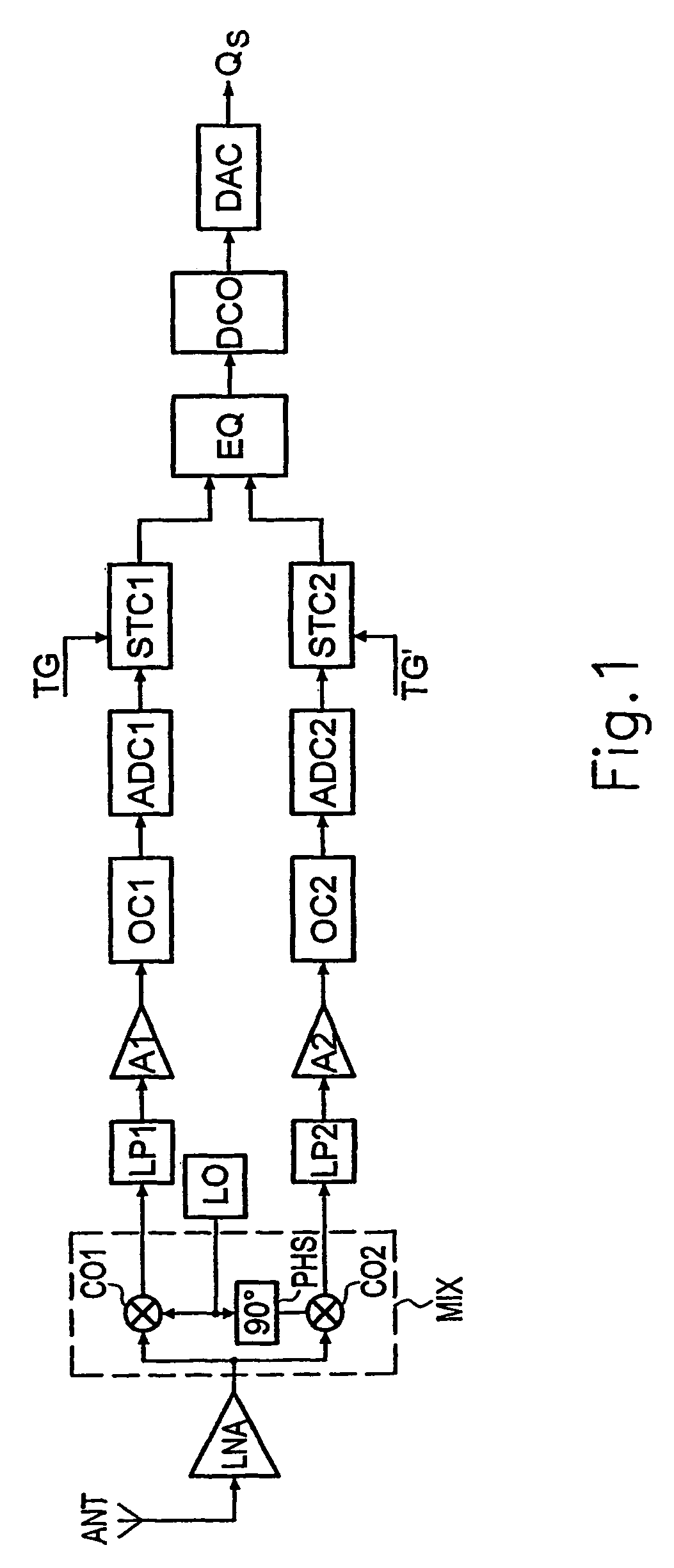
[0050]FIG. 1 will be used to explain the principle of a heterodyne receiver, and shows the signal path in this receiver, in the form of a block diagram.

[0051]The receiver has an antenna ANT via which a radio signal is received and is passed to a low-noise amplifier LNA. The output of the amplifier LNA is passed to a mixer MIX, which directly down-mixes the received signal to a baseband, and splits the received signal into I and Q branches. For this purpose, the mixer MIX has two mixing stages CO1 and CO2, which are driven by the carrier frequency of the received signal, phase-shifted through 90° with respect to one another. The carrier frequency is produced in the oscillator LO, and is phase-shifted at the phase shifter PHS.

[0052]The two analog baseband outputs of the mixer MIX are spectrally formed in low-pass filters LP1 and LP2, respectively, and are amplified by means of respective amplifiers A1 and A2.

[0053]Optional analog DC offset connection stages OC1 and OC2 are illustrated...


PUM


Abstract

In a method to compensate for a step DC disturbance (1) in a baseband signal in a homodyne radio receiver, the time profile of the step DC disturbance within a burst is determined. In order to produce a step-corrected baseband signal, the determined time profile (2) is then calculated from the digitized baseband signal.

Description

CROSS REFERENCE TO RELATED APPLICATION[0001]This application is a continuation of copending International Application No. PCT / DE02 / 02033 filed Jun. 4, 2002, and claiming a priority date of Jun. 11, 2001, which designates the United States.TECHNICAL FIELD OF THE INVENTION[0002]The invention relates to a method to compensate for a step DC disturbance in a digital baseband signal in a homodyne radio receiver, in particular a homodyne mobile radio receiver.DESCRIPTION OF THE RELATED ART[0003]Homodyne mobile radio receivers have become ever more important in recent years. Since homodyne mobile radio receivers have no intermediate frequency stage, a greater degree of integration can be achieved on the chip, thus reducing the costs of the mobile radio receiver.[0004]The main problem with the homodyne receiver architecture is that non-linearities in the radio-frequency (RF) receiver result in DC components occurring in the quadrature-demodulated signal at the output of the mixer stage, and ...

Claims


Application Information

Patent Timeline
Patent Type & Authority Patents(United States)
IPC IPC(8): H04L25/10H04B1/30
CPCH04B1/30
Inventor CUJE, MICHAELEIBL, STEFANHERZINGER, STEFANKRUGER, MARTINWU, XIAOFENGYANG, BIN
Owner INTEL CORP
Why Eureka
Try Eureka