
Method for apparatus for audio matrix decoding

a technology of audio matrix and decoding apparatus, which is applied in the direction of electrical apparatus, stereophonic system, stereophonic arrangment, etc., can solve the problems of 3 db separation between signals associated with adjacent directions and the disadvantage of crosstalk among decoded audio signals, and achieves a high degree of crosstalk cancellation, simple or low cost circuitry, and high performance.

Active Publication Date: 2007-10-09
DOLBY LAB LICENSING CORP
View PDF21 Cites 30 Cited by
  • Summary
  • Abstract
  • Description
  • Claims
  • Application Information

AI Technical Summary

Benefits of technology

[0010]It is a primary object of the invention to achieve a measurably and perceptibly high degree of crosstalk cancellation under a wide variety of input signal conditions, using circuitry with no special requirements for precision, and requiring no unusual complexity in the control path, both of which are found in the prior art.
[0011]It is another object of the invention to achieve such high performance with simpler or lower cost circuitry than prior art circuits.

Problems solved by technology

The decoded signals are approximations because matrix decoders suffer the well-known disadvantage of crosstalk among the decoded audio signals.
However, the inherent crosstalk in matrix decoders may result in only 3 dB separation between signals associated with adjacent directions.
Although prior art adaptive matrix decoders are intended to reduce crosstalk in the reproduced signals and more closely replicate the source signals, the prior art has done so in ways, many of which being complex and cumbersome, that fail to recognize desirable relationships among intermediate signals in the decoder that may be used to simplify the decoder and to improve the decoder's accuracy.

Method used


Image

  • Method for apparatus for audio matrix decoding
  • Method for apparatus for audio matrix decoding
  • Method for apparatus for audio matrix decoding

Examples


Embodiment Construction

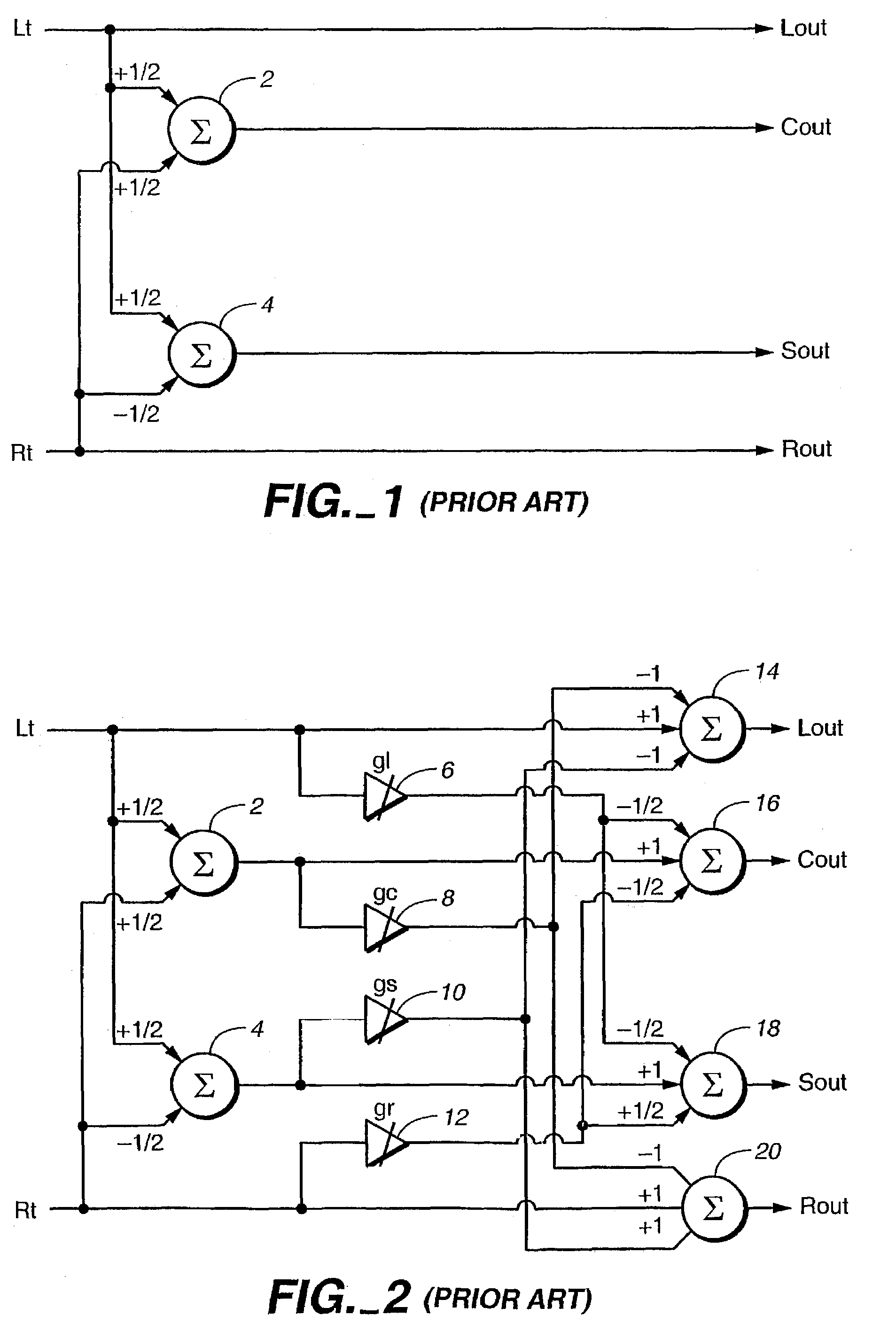
[0034]A passive decoding matrix is shown functionally and schematically in FIG. 1. The following equations relate the outputs to the inputs, Lt and Rt (“left total” and “right total”):

Lout=Lt  (Eqn. 1)

Rout=Rt  (Eqn. 2)

Cout=½*(Lt+Rt)  (Eqn. 3)

Sout=½*(Lt−Rt)  (Eqn. 4)

[0035](The “*” symbol in these and other equations throughout this document indicates multiplication.)

[0036]The center output is the sum of the inputs, and the surround output is the difference between the inputs. Both have, in addition, a scaling; this scaling is arbitrary, and is chosen to be ½ for the purpose of ease in explanation. Other scaling values are possible. The Cout output is obtained by applying Lt and Rt with a scale factor of +½ to a linear combiner 2. The Sout output is obtained by applying Lt and Rt with scale factors of +½ and −½, respectively, to a linear combiner 4.

[0037]The passive matrix of FIG. 1 thus produces two pairs of audio signals; the first pair is Lout and Rout; the second pair is Cout and ...


PUM


Abstract

A method derives at least three audio signals, each associated with a direction, from two input audio signals. In response to the two input signals, a passive matrix generates a plurality of passive matrix audio signals, including two pairs of passive matrix audio signals, a first pair of passive amtrix audio signals represent directions lying on a first axis and a second pair of passive matrix audio signals represent direction lying on a second axis, the first and second aces being substantially at ninety degrees to ach other. The pairs of passive matrix audio signals are processed to derive a plurality of matrix coefficients therefrom, The processing includes deriving a pair of intermediate signals and urging each pair of intermediate signals toward equality in response to a respective error signal. At least three output signals are produced by matrix multiplying the two input signals by the matrix coefficients.

Description

[0001]The invention relates to audio signal processing. In particular, the invention relates to “multidirectional” (or “multichannel”) audio decoding using an “adaptive” (or “active”) audio matrix method that derives three or more audio signal streams (or “signals” or “channels”) from a pair of audio input signal streams (or “signals” or “channels”). The invention is useful for recovering audio signals in which each signal is associated with a direction and was combined into a fewer number of signals by an encoding matrix. Although the invention is described in terms of such a deliberate matrix encoding, it should be understood that the invention need not be used with any particular matrix encoding and is also useful for generating pleasing directional effects from material originally recorded for two-channel reproduction.TECHNICAL FIELD[0002]Audio matrix encoding and decoding is well known in the prior art. For example, in so-called “4-2-4” audio matrix encoding and decoding, four ...

Claims


Application Information

Patent Timeline
Patent Type & Authority Patents(United States)
IPC IPC(8): H04R5/00H04S3/02
CPCH04S3/02
Inventor FOSGATE, JAMES W.VERNON, STEPHEN DECKERANDERSEN, ROBERT L.
Owner DOLBY LAB LICENSING CORP
Learn More