Blow-by gas and purge gas treating device in intake valve lift variable engine

a technology of purge gas treatment and intake valve, which is applied in the direction of liquid fuel feeders, machines/engines, combustion air/fuel air treatment, etc., can solve the problems that the generation of negative pressure in the intake system cannot be expected, and achieve the effect of simplifying the structure, good efficiency and simplifying the line arrangemen

Inactive Publication Date: 2007-10-16
HONDA MOTOR CO LTD
View PDF8 Cites 17 Cited by
  • Summary
  • Abstract
  • Description
  • Claims
  • Application Information

AI Technical Summary

Benefits of technology

[0009]With the first feature of the present invention, the blow-by gas is sucked by the first pump and pressurizingly transferred to the intake system, and the purge gas is mixed by the second pump into the pressurizingly transferred blow-by gas. Therefore, even in a non-throttle operation where a negative pressure is not generated in the intake system, the blow-by gas and the purge gas can be reliably guided to the intake system, and moreover only one pipe line is provided for guiding the blow-by gas and the purge gas to the intake system, thereby simplifying the line arrangement.
[0018]According to a tenth feature of the present invention, in addition to the ninth feature, the pump is a non-lubrication dry pump. With the tenth feature, since the pump is a dry pump, oil removing means such as an oil separator is not required on the downstream side of the pump, thereby greatly simplifying the system.

Problems solved by technology

Therefore, in the intake valve lift variable engine disclosed in the Japanese Patent Application Laid-open No. 2005-9487, generation of a negative pressure in the intake system can not be expected since the amount of intake air is regulated by opening / closing control of an intake valve.

Method used


Image

  • Blow-by gas and purge gas treating device in intake valve lift variable engine
  • Blow-by gas and purge gas treating device in intake valve lift variable engine
  • Blow-by gas and purge gas treating device in intake valve lift variable engine

Examples


Embodiment Construction

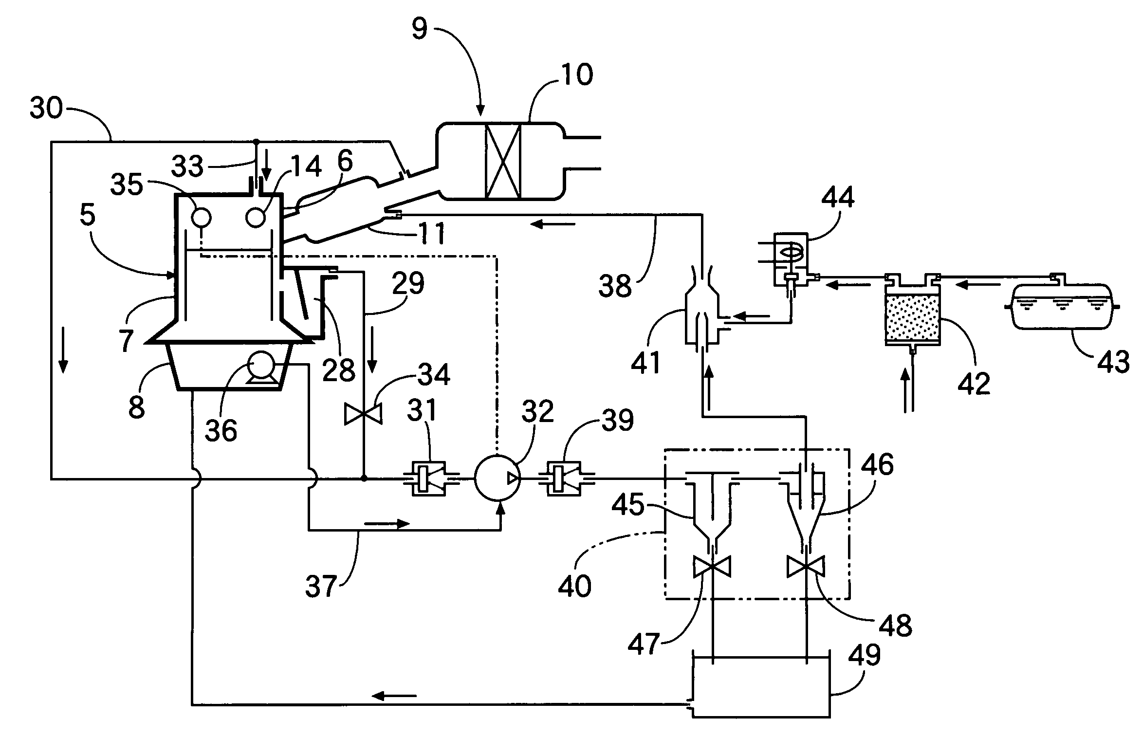
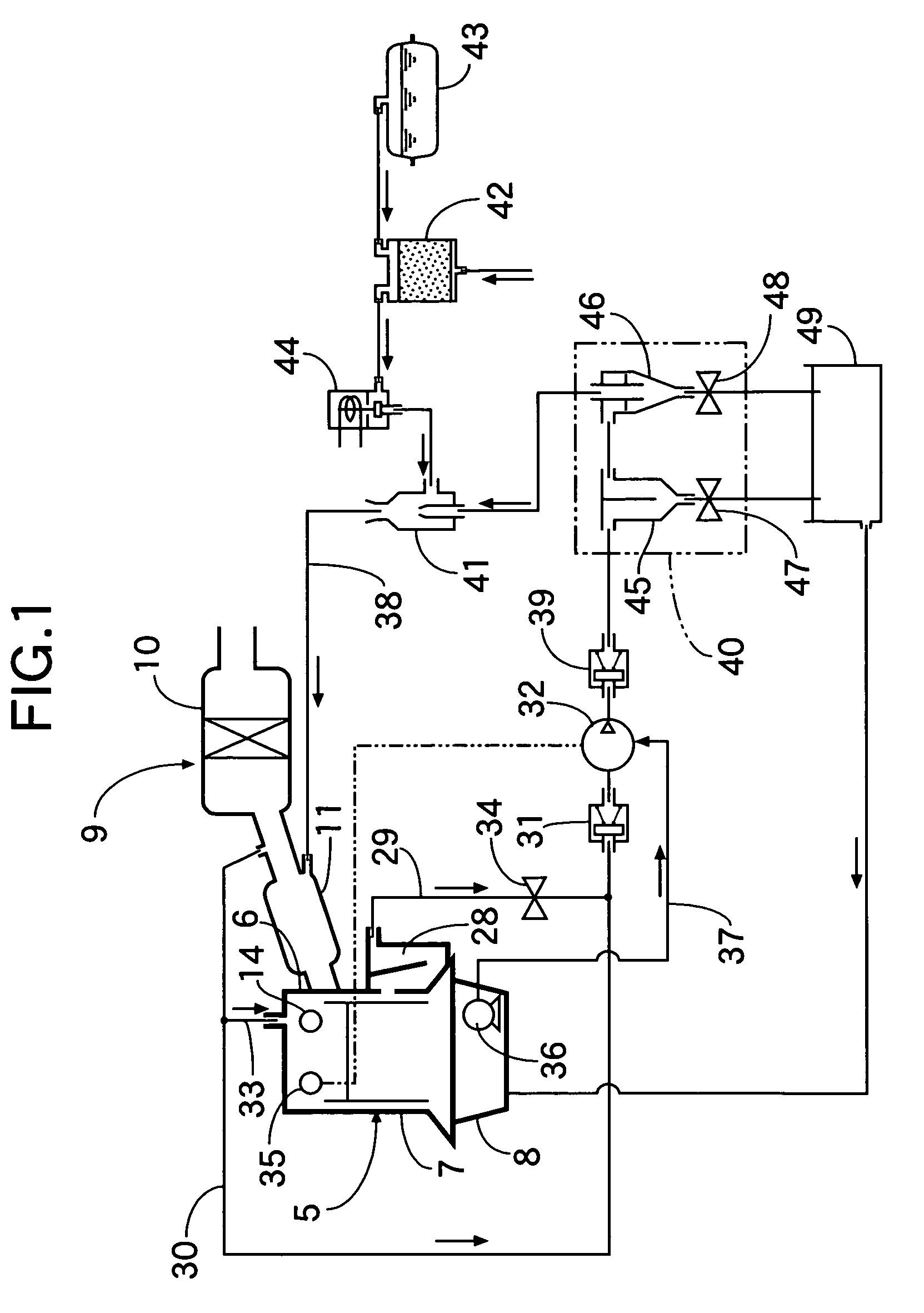
[0024]A first embodiment of the present invention will be described referring to FIGS. 1 to 3. As shown in FIG. 1, an intake system 9 has an air cleaner 10 for purifying air from the outside and an intake chamber 11 connected to the air cleaner 10 on the downstream side, and is connected to a cylinder head 6 of an engine body 5. No throttle valve is provided in this intake system 9.

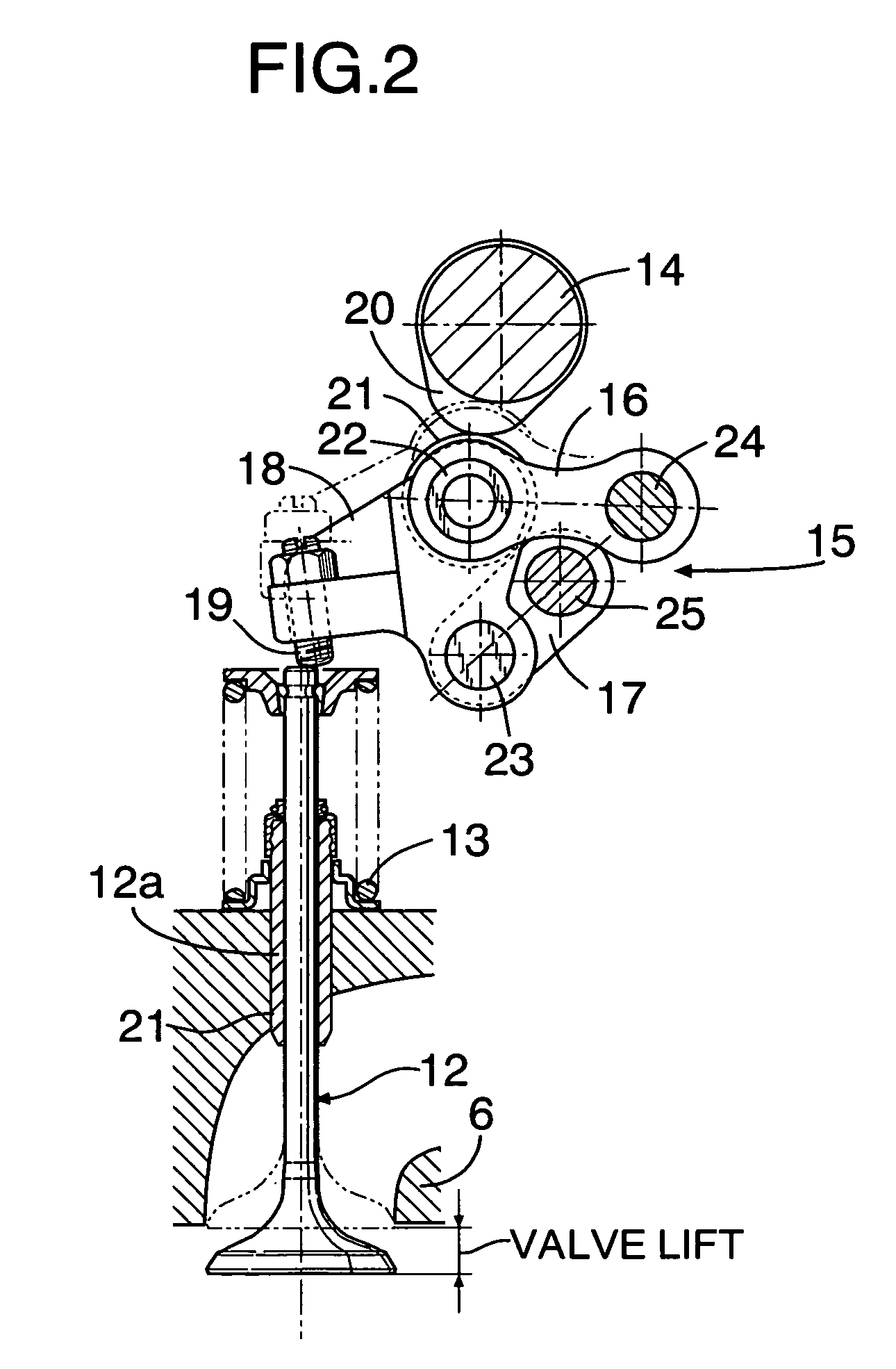
[0025]In FIG. 2, an intake valve 12 is disposed on the cylinder head 6 to be capable of opening / closing operation while being urged by a valve spring 13 in the valve-closing direction, and the intake valve 12 is driven by an intake-side camshaft 14 via a lift variable mechanism 15. The lift variable mechanism 15 has a first link arm 16, a second link arm 17 arranged below the first link arm 16, and a rocker arm 18.

[0026]A tappet screw 19 is screwed into one end of the rocker arm 18 to be adjustable in the advanced / retreating positions such that the tappet screw 19 contacts from above with an upper end of ...


PUM


Abstract

In an intake valve lift variable engine including: an engine body; a cylinder head; an intake valve which is disposed in the cylinder head and which is controlled to be open and close so as to regulate the amount of intake air; and an intake system having no throttle valve and connected to the cylinder head, blow-by gas is sucked from a crank case of the engine body into a first pump and pressurizingly transferred by the first pump to the side of the intake system, and purge gas from a canister is mixed into the blow-by gas pressurizingly transferred by the first pump. Thus, the blow-by gas and the purge gas are guided to the intake system.

Description

RELATED APPLICATION DAT[0001]The present invention is based upon Japanese priority application Nos. 2005-55473 and 2005-55474, which are hereby incorporated in their entirety herein by reference.BACKGROUND OF THE INVENTION[0002]1. Field of the Invention[0003]The present invention relates to an intake valve lift variable engine comprising: an engine body; a cylinder head; an intake valve which is disposed in the cylinder head and which is controlled to be open and close so as to regulate the amount of intake air; and an intake system having no throttle valve and connected to the cylinder head, and particularly to a device for treating blow-by gas from a crank case and purge gas purged from a canister.[0004]2. Description of the Related Art[0005]The Japanese Patent Application Laid-open No. 2005-9487 discloses an intake valve lift variable engine in which a throttle valve is not interposed in an intake system by regulating the amount of intake air sucked by opening / closing control of ...

Claims


Application Information

Patent Timeline
Patent Type & Authority Patents(United States)
IPC IPC(8): F02B25/06F01L1/34
CPCF01M13/04F02M25/06F02M25/08F01M2013/0072F01M2013/026Y02T10/121F01M2013/0433F01M2013/0427Y02T10/12
Inventor KAKIMOTO, KAZUHITOSATO, HISASHI
Owner HONDA MOTOR CO LTD
Why Eureka
Try Eureka