Injecting a fluid into a borehole ahead of the bit

a technology of injecting fluid and borehole, which is applied in the direction of drilling pipes, borehole/well accessories, cutting machines, etc., can solve the problems of high risk of nozzle plugging, highly undesirable to attempt pumping, and not seriously considered, and achieve the effect of safe introduction

Inactive Publication Date: 2007-10-16
SCHLUMBERGER TECH CORP
View PDF32 Cites 54 Cited by
  • Summary
  • Abstract
  • Description
  • Claims
  • Application Information

AI Technical Summary

Benefits of technology

[0009]It is an object of the present invention to provide a method for introducing a fluid into a borehole, wherein fluid can be safely introduced through the drill string with a drill bit attached at its low

Problems solved by technology

It is considered highly undesirable to attempt pumping of a fluid of high density or viscosity and/or comprising coarse material through the drill string with a drill bit attached.
However, the fluid would need to be forced through the bit nozzles, and there is a high risk for the nozzles to plug up due to the high shear, rapid pressure drop, and small orifi

Method used


Image

  • Injecting a fluid into a borehole ahead of the bit
  • Injecting a fluid into a borehole ahead of the bit
  • Injecting a fluid into a borehole ahead of the bit

Examples


Embodiment Construction

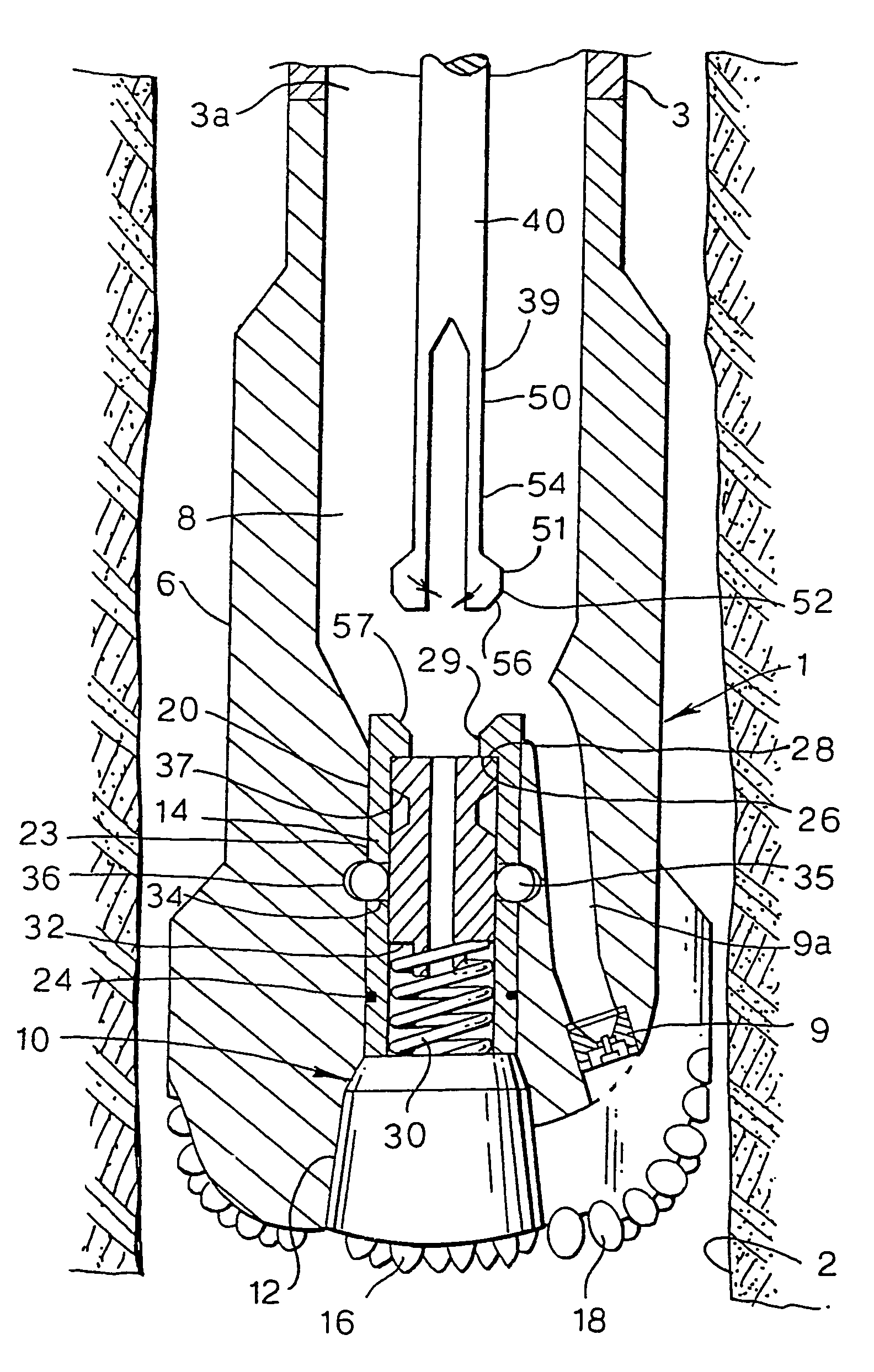
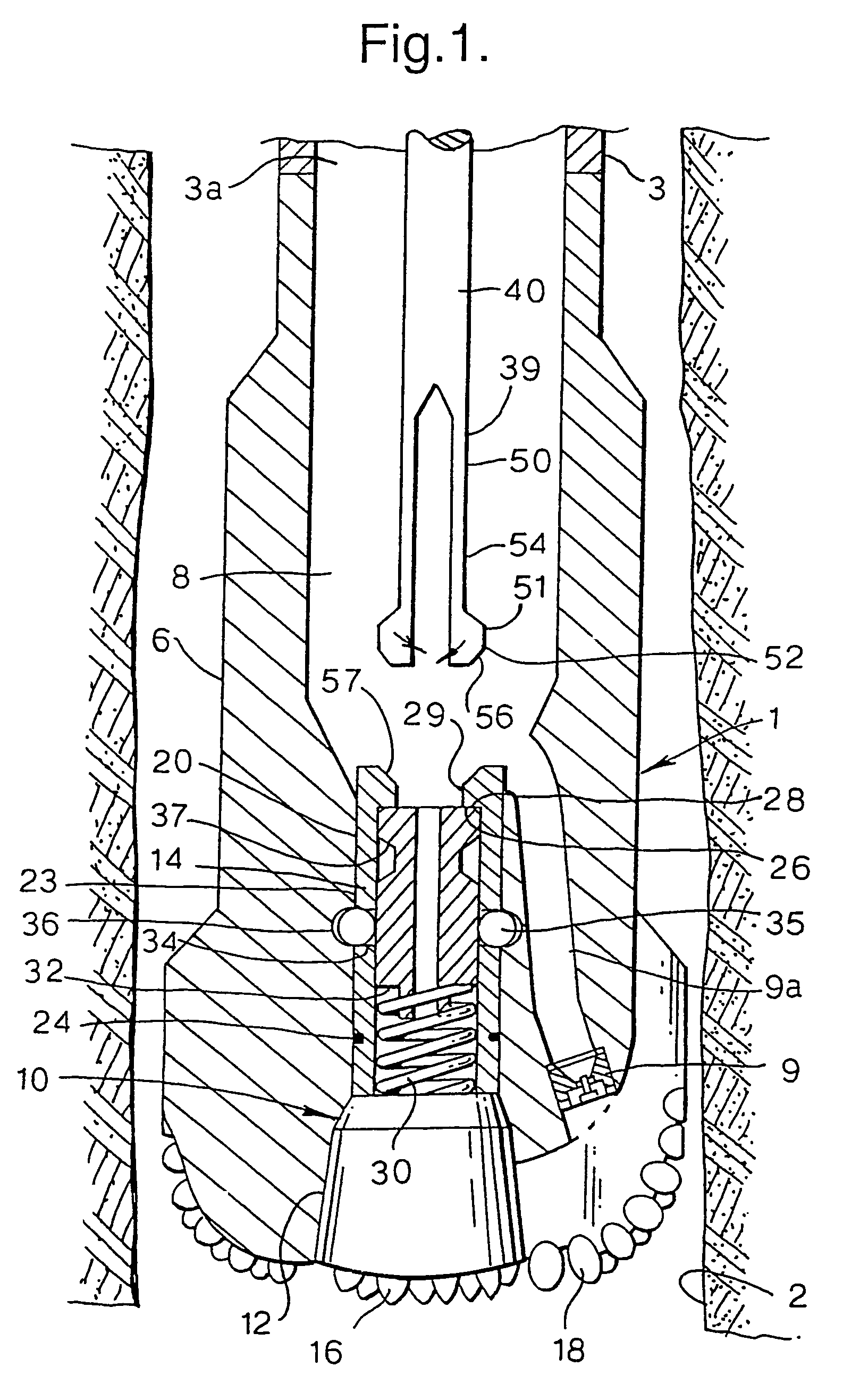
[0035]With reference to FIG. 1, basic features of the present invention will now be discussed. FIG. 1 shows schematically a longitudinal cross-section of a rotary drill bit 1, which is a suitable embodiment for use with the present invention. The drill bit 1 is shown in the borehole 2, and is attached to the lower end of a drill string 3 at the upper end of the bit body 6. The bit body 6 of the drill bit 1 has a central longitudinal passageway 8 providing fluid communication, and in particular passage for a tool, between the interior 3a of the drill string 3 and the borehole 2 exterior of the drill bit 1, as will be pointed out in more detail below. Bit nozzles are arranged in the bit body 6. Only one nozzle with insert 9 is shown for the sake of clarity. The nozzle 9 is connected to the passageway 8 via the nozzle channel 9a.

[0036]The drill bit 1 is further provided with a removable closure element 10, which is shown in FIG. 1 in its closing position with respect to the passageway...


PUM


Abstract

A method and system for introducing a fluid into a borehole, in which there is arranged a tubular drill string including a drill bit, wherein the drill bit is provided with a passageway between the interior of the drill string and the borehole, and with a removable closure element for selectively closing the passageway in a closing position, and wherein there is further provided a fluid injection tool comprising a tool inlet and a tool outlet, the method comprising passing the fluid injection tool through the drill string to the closure element, and using it to remove the closure element from the closing position, passing the fluid injection tool outlet through the passageway, and introducing the fluid into the borehole from the interior of the drill string through fluid injection tool into the borehole.

Description

FIELD OF THE INVENTION[0001]The present invention relates to a method and system for introducing a fluid into a borehole formed in an underground earth formation. The term fluid is used in the specification and in the claims to refer to any material that can be pumped through a tubular drill string, for example cement, lost circulation material, or cleaning fluid. The fluid can also include solid particles.BACKGROUND OF THE INVENTION[0002]Lost circulation material is any material, which can be used to block fractures in underground formations and is generally of a coarser nature.SUMMARY OF THE INVENTION[0003]The invention relates in particular to introducing such a fluid into the borehole ahead of the drill bit at the lower end of the drill string.[0004]In the course of a drilling operation, in particular when drilling an oil or gas well, it is on occasion desirable to pump a fluid into the borehole. For example, when drilling into a fractured or porous zone, it is desired to cure l...

Claims


Application Information

Patent Timeline
IPC IPC(8): E21B10/60E21B10/62E21B21/10
CPCE21B10/60E21B21/10E21B10/62
Inventor RUNIA, DOUWE JOHANNESSMITH, DAVID GEORGE LIVESEYWORRALL, ROBERT NICHOLAS
Owner SCHLUMBERGER TECH CORP
Why Eureka
Try Eureka