Suction device

a suction device and suction nozzle technology, applied in the direction of portable drilling machines, manufacturing tools, and well accessories, can solve the problems of reducing the suction capacity, reducing the suction path between the suction nozzle and the collection device, and high flow loss, so as to reduce the weight and cost, increase the suction capacity, and reduce the suction path. effect of reducing the length of the suction path

Inactive Publication Date: 2007-10-16
HILTI AG
View PDF42 Cites 55 Cited by
  • Summary
  • Abstract
  • Description
  • Claims
  • Application Information

AI Technical Summary

Benefits of technology

[0010]With the aeration device displacing together with the suction head in the same direction and by the same amount, the flow characteristics remain substantially constant during the drilling process. As a result, the suction device can be optimally adapted to the envisaged operation to achieve a maximal suction performance.
[0013]According to a particularly advantageous embodiment of the present invention, the guide is releaseably mounted on the drilling tool, which permits the use of the suction device with different drilling tools.
[0014]Advantageously, the aeration device is connectable with the power supply of the drilling tool, which eliminates the need for a separate power supply for the suction device. By connecting the aeration device with the power supply of the tool the device is used with, weight and costs are reduced.
[0016]Preferably, the suction pipe has a receiving chamber for a filter element, so that the material, which is produced during drilling consisting of drilling dust and drillings, can be produced relatively close to the suction nozzle. Thereby, the suction path can be noticeably reduced, which increases the suction capacity.
[0017]It is advantageous when the receiving chamber extends over almost the entire length of the suction pipe. This permits the use of a particularly long filter element with a correspondingly high filtering action.

Problems solved by technology

The drawback of the known suction device is that the suction path between the suction nozzle and the collection device is relatively long because of the flexible bent section of the suction conduit.
This leads to relatively high flow losses and a resulting reduction of the suction capacity.
Moreover, the drawback of the flexible, bent section of the suction conduit consists in that, on the one hand, flow characteristics change during the drilling operation and, on the other hand, disturbances in the operation of the suction device can occur because of possible bending of the flexible section during operation.

Method used


Image

  • Suction device
  • Suction device
  • Suction device

Examples


Embodiment Construction

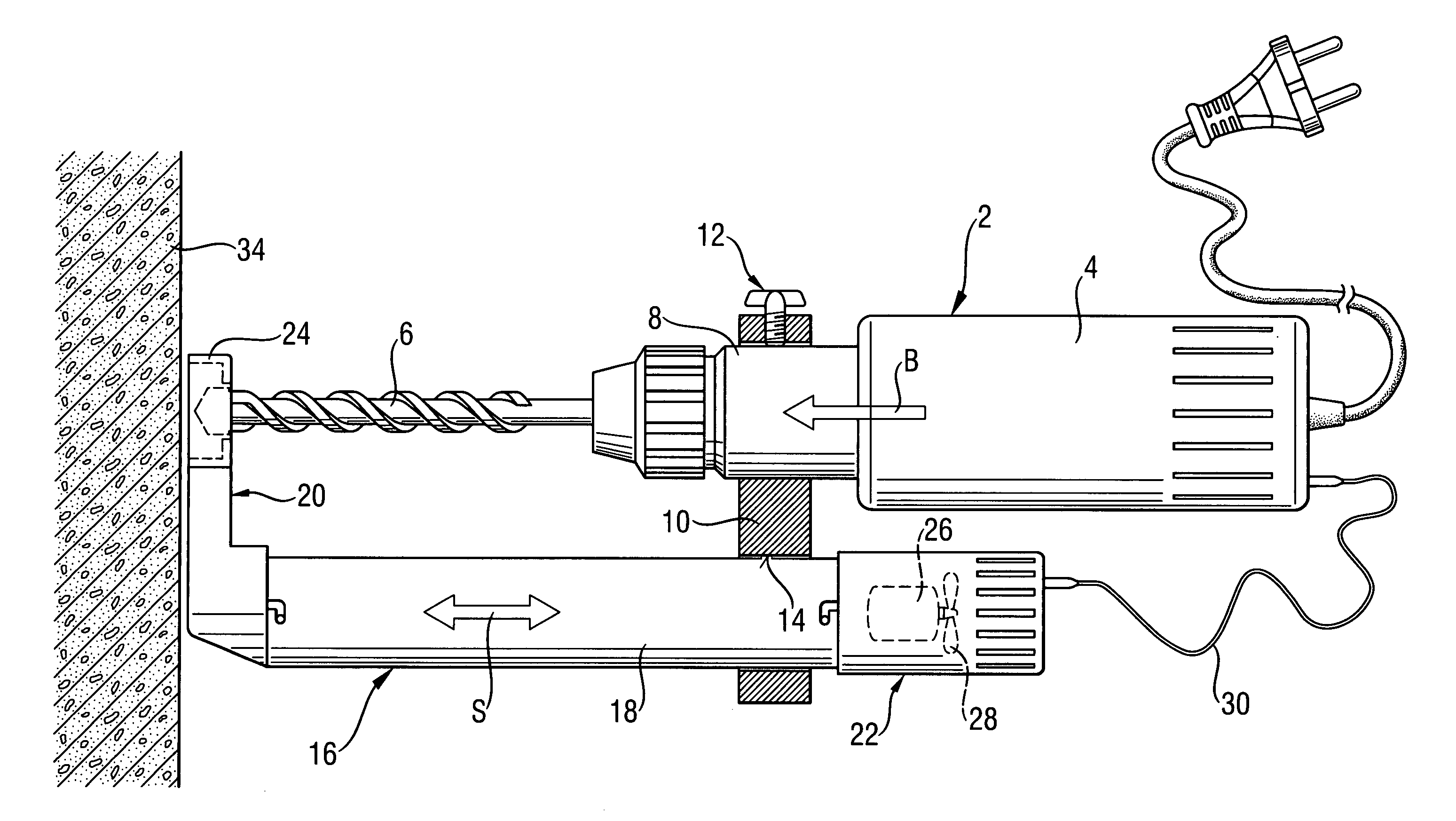
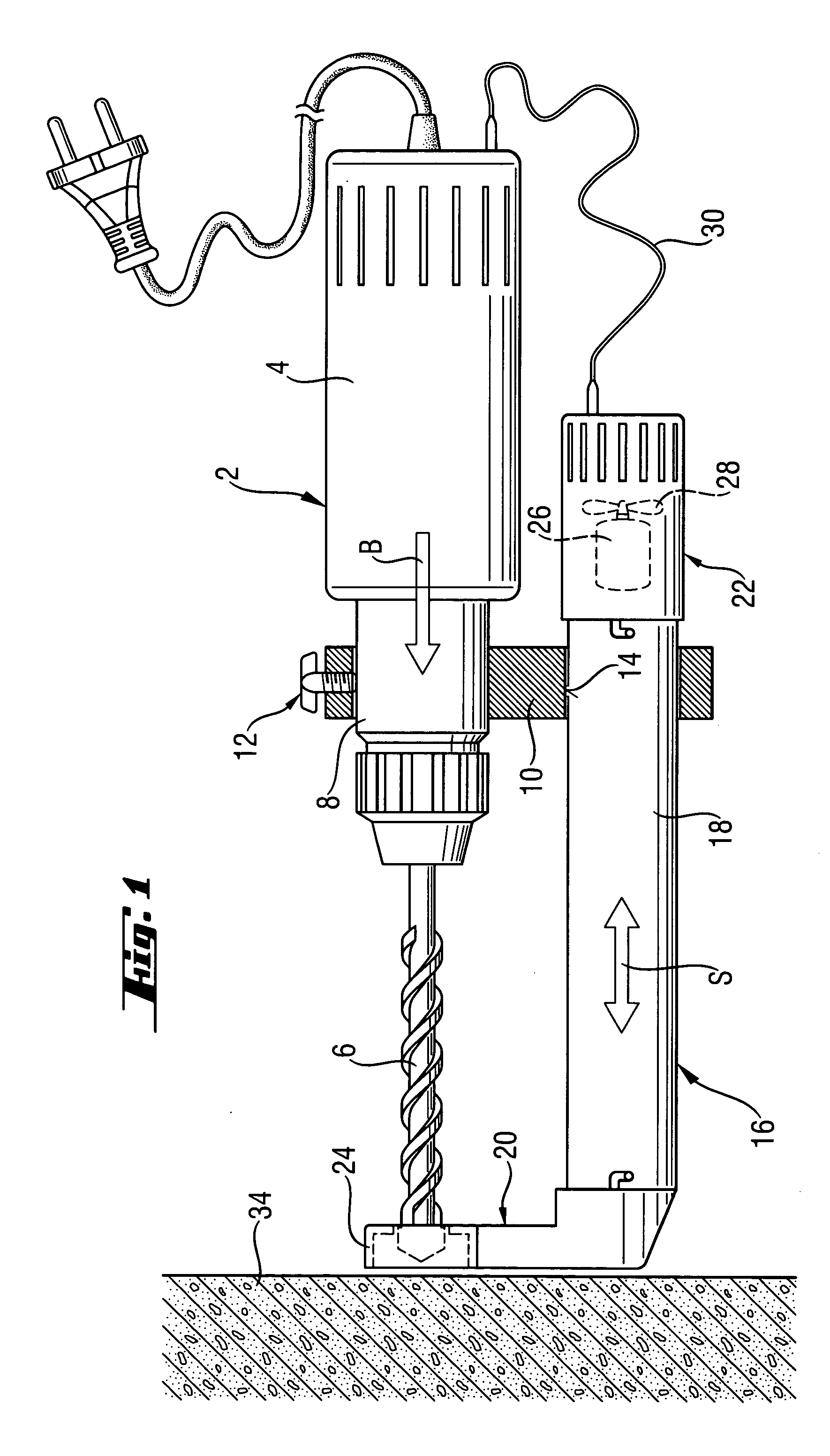
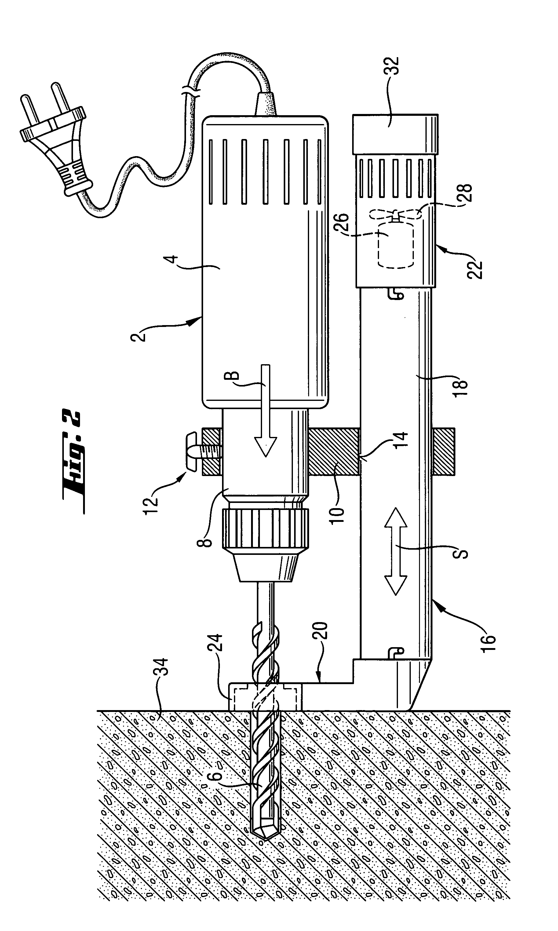
[0023]A drilling tool 2, which is shown in FIG. 1, includes a housing 4, a drill 6, and a cylindrical receiving region 8. Instead of an auxiliary handle, which is normally secured to the receiving region 8, a connection device 10 is releaseably secured to the cylindrical region. The attachment and release of the connection device 10 are effected with simple clamp means 12 of the connection device 10.

[0024]A suction device 16 is displaceably supported for displacement in a displacement direction S relative to the drilling tool 2 on a rigid suction pipe 18 that extends through a guide opening 14 of the connection device 10. The displacement direction S is substantially parallel to a drilling direction B of the drilling tool 2. The suction pipe 18 performs a double function. On the one hand, it serves as a stable guide for the suction device 16 and, on the other hand, it serves as a suction conduit for connecting the suction head 20 with an aeration device 22. The guide opening 14 func...


PUM

PropertyMeasurementUnit
displacementaaaaaaaaaa
flexibleaaaaaaaaaa
suction capacityaaaaaaaaaa

Abstract

A suction device that is used with a power drilling tool for aspirating material removable during operation of the drilling tool, and which includes a suction head (20) displaceable relative to the drilling tool (2) in a direction opposite a drilling direction (B) of the drilling tool (2), and an aeration device (22) fixedly connected by a suction conduit with the suction head (20) for joint displacement therewith.

Description

BACKGROUND OF THE INVENTION[0001]1. Field of the Invention[0002]The present invention relates to a suction device which is used with a power drilling tool for aspirating material removable during operation of the drilling tool such as drilling dust and drillings and which includes a suction head having a suction opening and displaceable relative to the drilling tool in a direction opposite a drilling direction of the drilling tool, an aeration device for producing a suction air current, and a suction conduit for connecting the suction head with the aeration device.[0003]2. Description of the Prior Art[0004]The advantage of the suction devices of the type described above consists in that a suction nozzle, which forms part of the suction head and is displaceably supported on the drilling tool, is displaced during the drilling process, in the direction opposite the drilling direction by the same amount the drill penetrates into the drilled surface. As a result of the displacement of th...

Claims


Application Information

Patent Timeline
Patent Type & Authority Patents(United States)
IPC IPC(8): B23B47/34B28D7/02B23Q11/00
CPCB23Q11/0046Y10T408/50Y10T408/564
Inventor STOERIG, THORSTEN
Owner HILTI AG
Why Eureka
Try Eureka