
Fan and impeller thereof

a technology of impeller and fan, which is applied in the direction of marine propulsion, vessel construction, and other chemical processes, can solve the problems of unclean appearance of the fan, inconvenient use, and easy separation from the tool, and achieve the effect of improving the rotation stability of the fan and increasing the reliability and lifetime of the fan

Active Publication Date: 2007-10-16
DELTA ELECTRONICS INC
View PDF14 Cites 25 Cited by
  • Summary
  • Abstract
  • Description
  • Claims
  • Application Information

AI Technical Summary

Benefits of technology

[0009]In view of the foregoing, the present invention provides a fan and an impeller thereof for improving the rotation stability of the fan, so as to increase reliability and lifetime of the fan.
[0010]In addition, the present invention provides a fan and an impeller thereof for facilitating easy separation of the balancing object from the tool, so as to simplify the adjusting process.
[0013]As mentioned above, a fan and an impeller thereof according to the present invention has at least one corner disposed in the balancing portion. When the fan is rotating, the balancing object is constrained at the turning part so as to prevent the balancing object from being spilled. As a result, the appearance of the fan is clean and the rotation stability of the fan can be enhanced. Therefore, product reliability and lifetime of the fan can be increased. Furthermore, when users utilize a tool to put the balancing object into the balancing portion, the corner provides the function of a scraping effect, so as to facilitate easy separation of the balancing object from the tool at the corner.

Problems solved by technology

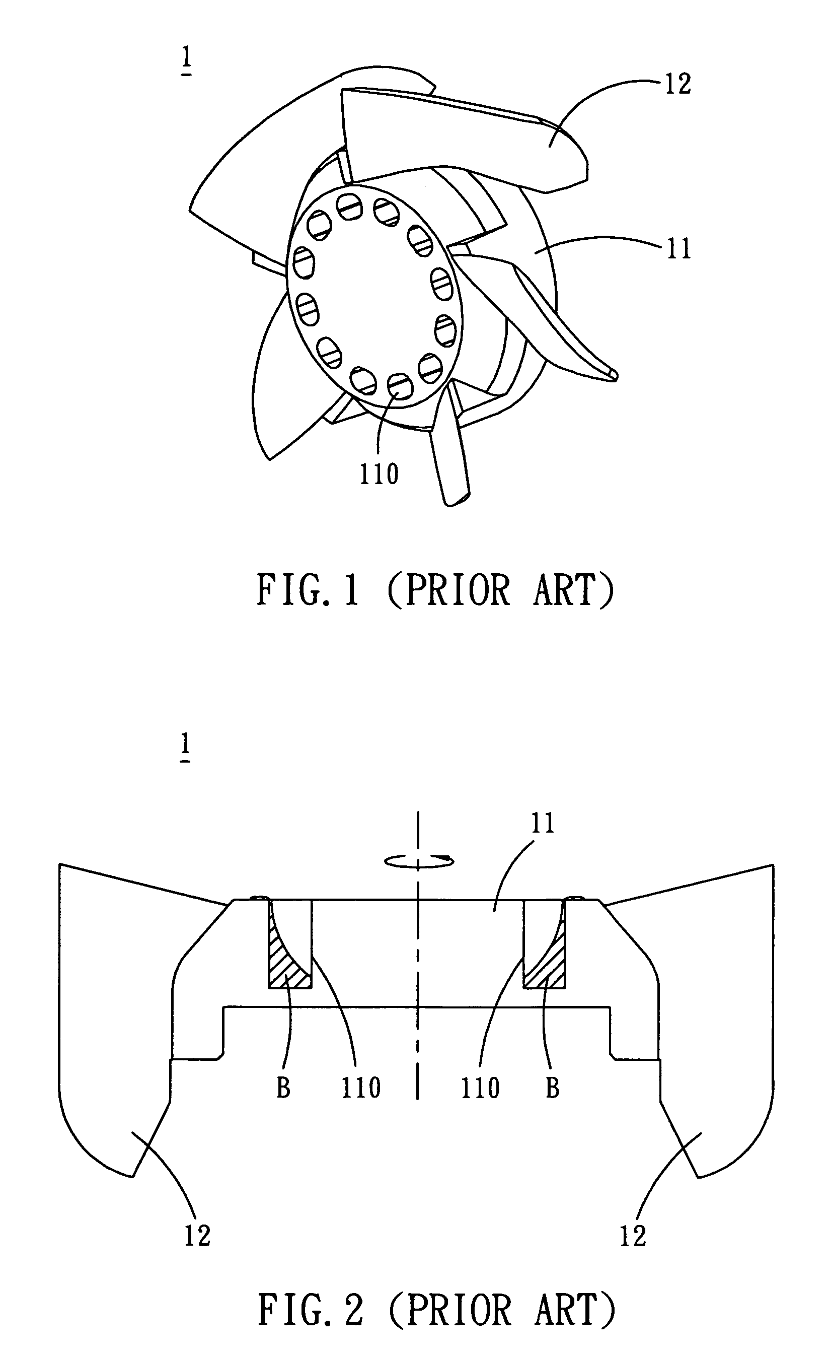
However, while using the tool to put the balancing object B into the balancing portion 110, the balancing object B is not easily separated from the tool due to high viscosity of the balancing object B. This is inconvenient to users.
Accordingly, the appearance of the fan is unclean, and the rotation balance and reliability of the fan are destroyed.

Method used


Image

  • Fan and impeller thereof
  • Fan and impeller thereof
  • Fan and impeller thereof

Examples


Embodiment Construction

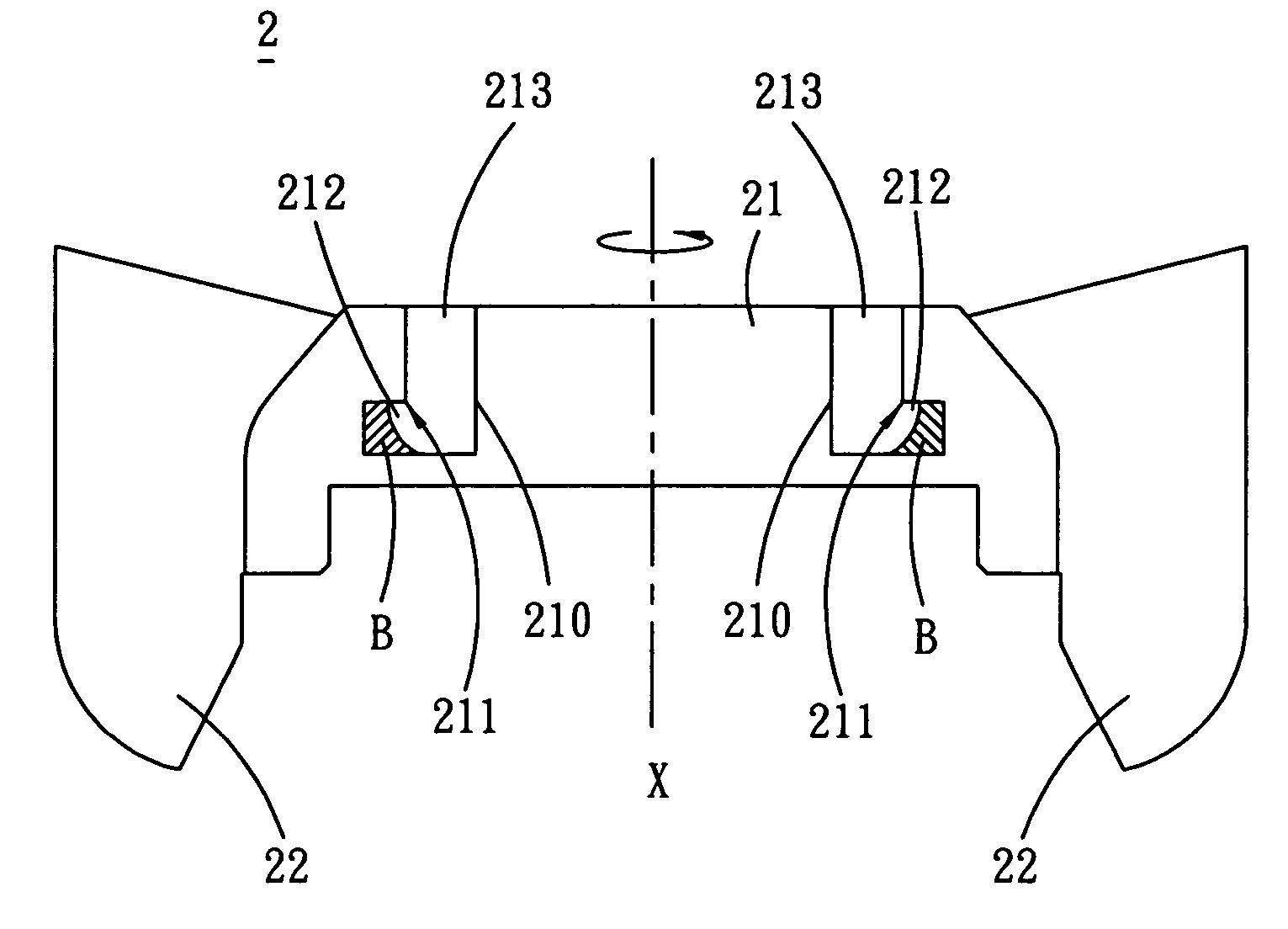
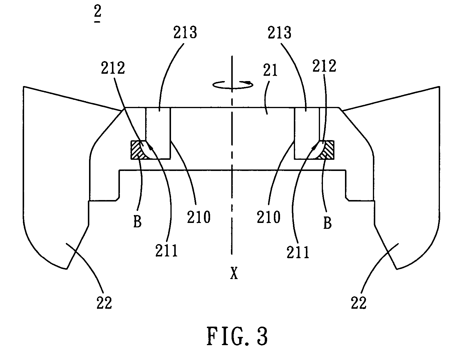
[0024]Referring to FIG. 3, an impeller 2 according to a first preferred embodiment of the present invention includes a hub 21 and at least one blade 22 disposed around the hub 21. The hub 21 has at least one balancing portion 210 disposed on the hub 21 and arranged with respect to a center X of the hub 21.

[0025]Each of the balancing portions 210 has at least one corner 211, a turning part 212 and an opening part 213. The corner 211 is located and connected between the opening part 213 and the turning part 212. A direction of the corner 211 is toward the radial direction of the center X of the hub 21. In this embodiment, the balancing portion 210 may have different configurations in accordance with the practical requirement. The opening part 213 may have a cross section with a circular (FIG. 4f-1), elliptical (FIG. 4f-2), triangular (FIG. 4f-3), rectangular (FIGS. 4f-4) or polygonal (FIG. 4f-5) shape, and a cross section of the turning part 212 may have a different shape and dimensio...


PUM


Abstract

An impeller includes a hub and at least one blade. In this case, the hub has at least one balancing portion disposed on hub and arranged with respect to a center of the hub. The balancing portion has at least one corner. The blades are disposed around the hub. In addition, a fan including the impeller is also provided. The impeller and the fan can enhance the rotation stability. As a result, the product reliability and lifetime can be increased. Furthermore, the impeller and the fan facilitate the balancing object to be separated from the tool at the corner.

Description

[0001]This non-provisional application claims priority under U.S.C. § 119(a) of patent application No. 094117444 filed in Taiwan, R.O.C. on May 27, 2005, the entire contents of which are hereby incorporated by reference.BACKGROUND OF THE INVENTION[0002]1. Field of Invention[0003]The present invention relates to a fan and an impeller thereof and, in particular, to a fan and an impeller thereof with rotation stability.[0004]2. Related Art[0005]Fans are now in widespread use for heat dissipation, and are typically driven by motors so as to rotate and produce a pressure gradient, thereby generating a fluid flow. Consequently, it is an essential requirement for the fans to provide a good rotation balance.[0006]Referring to FIGS. 1 and 2, a conventional fan includes an impeller 1 and a motor (not shown) for driving the impeller 1. The impeller 1 includes a hub 11 and at least one blade 12 disposed around the hub 11. In a practical manufacture, the impeller 1 is a one-piece molding by inje...

Claims


Application Information

Patent Timeline
Patent Type & Authority Patents(United States)
IPC IPC(8): F03B3/12
CPCF04D29/329F04D29/662Y10S416/50
Inventor YU, PO-HAOCHANG, SHUN-CHENHUANG, WEN-SHI
Owner DELTA ELECTRONICS INC
Learn More