
Light emitting diode and method of fabricating the same

a technology of light-emitting diodes and manufacturing methods, which is applied in semiconductor/solid-state device manufacturing, electrical equipment, semiconductor devices, etc., can solve the problems of low light utility efficiency and low luminescence character of p-type electrodes, low light efficiency of p-type electrodes, and low light output efficiency, so as to improve light output efficiency and light-emitting efficiency.

Active Publication Date: 2007-10-16
SAMSUNG ELECTRONICS CO LTD
View PDF3 Cites 12 Cited by
  • Summary
  • Abstract
  • Description
  • Claims
  • Application Information

AI Technical Summary

Benefits of technology

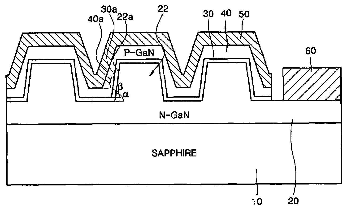
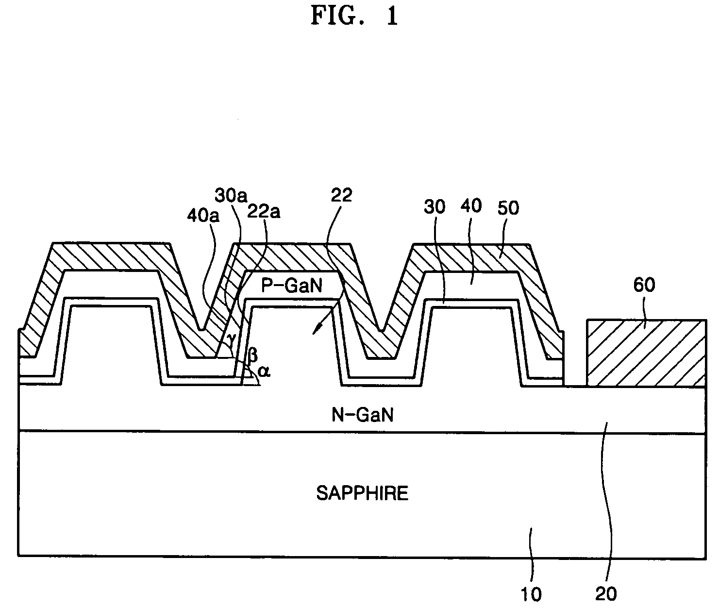
[0008]The present invention may provide a light emitting diode (LED) and a method of fabricating the LED with an improved structure for increasing the light emitting efficiency and the light output efficiency.
[0012]According to the present invention, an LED with improved light emitting efficiency and light output efficiency can be obtained.

Problems solved by technology

However, the p-type electrode formed of Ni and Au is semi-transparent, and the TLED in which the p-type electrode is applied has a low light utility efficiency and a low luminescence character.
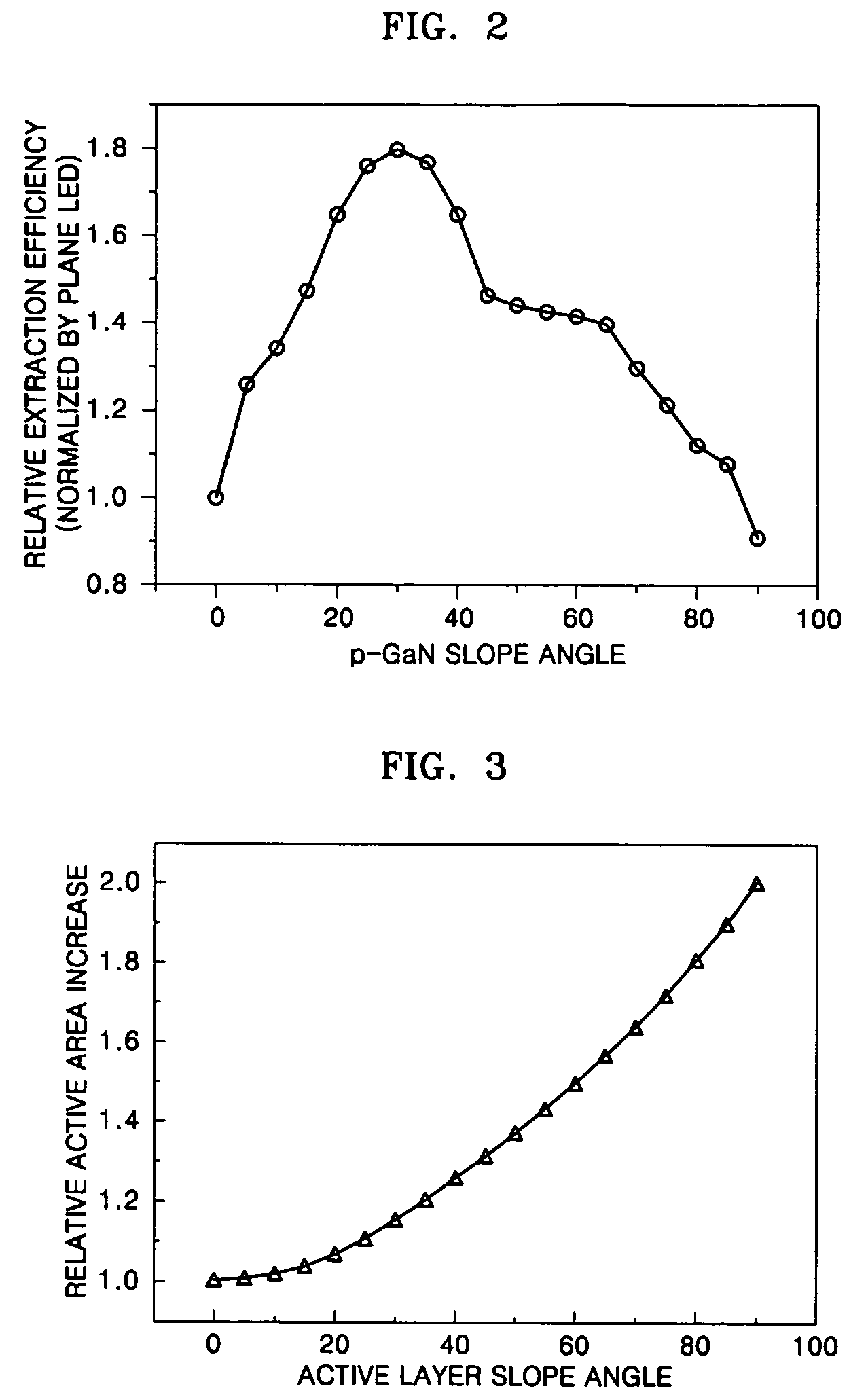
However, in an uneven structure obtained by etching a p-GaN layer, current injection may be problematic because of the thickness reduction of the p-GaN layer.
Also, in an uneven structure obtained by etching the lower part of the active layer, light emitting efficiency may be reduced due to the reduction of the area of the active layer.
In addition, an electric insulation layer is required between an n-GaN layer and a p-GaN layer, thereby complicating the electrode formation process.

Method used


Image

  • Light emitting diode and method of fabricating the same
  • Light emitting diode and method of fabricating the same
  • Light emitting diode and method of fabricating the same

Examples


Embodiment Construction

[0021]Preferred embodiments of the present invention will now be described with reference to the attached drawings. In the drawings, the thicknesses of layers and regions are exaggerated for clarity.

[0022]FIG. 1 is a schematic cross-sectional view of a light emitting diode (LED) according to an embodiment of the present invention. Referring to FIG. 1, the LED includes a n-GaN layer 20 alternately disposed on a substrate 10, an active layer 30, a p-GaN layer 40, a p-electrode 50, and an n-electrode 60 formed on a predetermined surface area of the p-GaN layer 20. In the present embodiment, light is emitted from the active layer 30 and is reflected to the p-electrode 50 formed on the p-GaN layer 40, and the reflected light is emitted through the substrate 10.

[0023]The n-GaN layer 20 is formed to have a plurality of protrusions 22, thereby having an uneven surface. The protrusions 22 have a side 22a inclined with respect to the upper surface of the substrate 10 at a first inclination an...


PUM


Abstract

A light emitting diode (LED) and a method are provided for fabricating the a LED with an improved structure for better light emitting efficiency and better light output performance. The LED includes an n-GaN layer formed on a substrate to have a plurality of protrusions, thereby having an uneven surface, wherein a side surface of the protrusions is inclined with a first inclination angle α (35°≦α≦90°) with respect to an upper surface of the substrate; an active layer conformally formed on the surface of the n-GaN layer, wherein the surface of the active layer formed on the side surface of the protrusions is inclined with a second inclination angle β (35°≦β≦α) with respect to the upper surface of the substrate; a p-GaN layer conformally formed on the surface of the active layer, wherein the surface of the p-GaN layer formed on the surface of the inclined portion of the active layer is inclined with a third inclination angle γ (20°≦γ<β) with respect to the upper surface of the substrate; and an n-electrode formed on a predetermined area of the n-GaN layer to correspond to the p-electrode.

Description

CROSS-REFERENCE TO RELATED PATENT APPLICATION[0001]This application claims the benefit of Korean Patent Application No. 10-2005-0062926, filed on Jul. 12, 2005, in the Korean Intellectual Property Office, the disclosure of which is incorporated herein in its entirety by reference.BACKGROUND OF THE DISCLOSURE[0002]1. Field of the Disclosure[0003]The present disclosure relates to a light emitting diode and a method of fabricating the same, and more particularly, to a light emitting diode and a method of fabricating the same with an improved structure capable of increasing the light emitting efficiency and the light output efficiency.[0004]2. Description of the Related Art[0005]A light emitting diode (LED) is a semiconductor device, which emits light by electrons moving from a point of high energy level to a point of low energy level when an electric power is applied to it. A LED consumes 1 / 12 of the power of the conventional light source, and has 100-time longer life time, and 1000-ti...

Claims


Application Information

Patent Timeline
Patent Type & Authority Patents(United States)
IPC IPC(8): H01L27/15H01L29/22H01L33/22H01L33/32
CPCH01L33/24H01L33/0075
Inventor LEE, JEONG-WOOKLENIACHINE, VASSILISONG, MI-JEONGYOON, SUK-HOKIM
Owner SAMSUNG ELECTRONICS CO LTD
Learn More