Multi-turn element RF coil array for multiple channel MRI

a multi-turn element, coil array technology, applied in the field of magnetic resonance imaging (mri), can solve the problems of reducing the loading factor, affecting the accuracy of k-space matrix filling, and affecting the accuracy of mri filling, etc., to achieve high loading factor and high q

Inactive Publication Date: 2007-10-16
THE JOHN HOPKINS UNIV SCHOOL OF MEDICINE +1
View PDF10 Cites 49 Cited by
  • Summary
  • Abstract
  • Description
  • Claims
  • Application Information

AI Technical Summary

Problems solved by technology

Although many improvements and variants have been made in this general area, the speed with which the k-space matrix may be filled is limited.
A drawback of the SENSE technique, for example, results when the component coil sensitivities are either insufficiently well characterized or insufficiently distinct from one another.
These instabilities may manifest as localized artifacts in the reconstructed image, or may result in degraded SNR.
Additionally, image artifacts are also attributable to the mutual couplings between coils in a cluster of closely situated surface coils, which have been separately tuned and matched.
The mutual couplings between the coils generate coupled modes, which cause splitting in the coils' resonant spectrum.
Consequently, the coils become detuned and mismatched, causing reductions in the SNR.
However, there are a number of design challenges in providing the capability of multiple receive channels and multiple coils.
Additionally, the coil size and corresponding arrangement within a coil array will present inherent inductive coupling and sensitivity issues which both can negatively impact the quality (Q) and loading factors of the coils, thereby limiting overall SNR performance of the coils and MRI system during imaging.
However, spiral or multiple-looped coils used in MRI systems operating at or above 30 MHz may negatively impact the overall performance of the coils and MRI system during imaging.

Method used


Image

  • Multi-turn element RF coil array for multiple channel MRI
  • Multi-turn element RF coil array for multiple channel MRI
  • Multi-turn element RF coil array for multiple channel MRI

Examples


Embodiment Construction

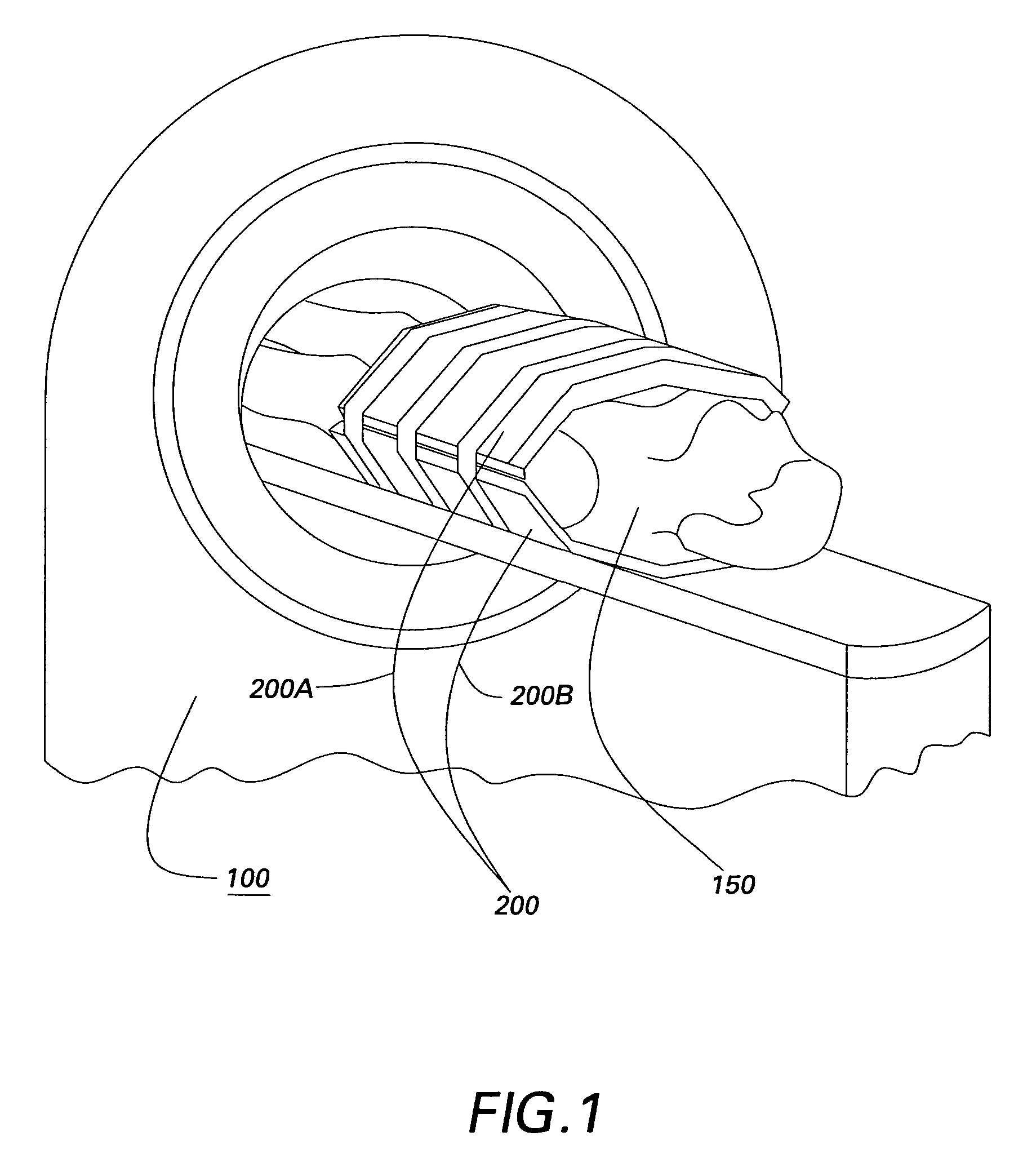
[0018]Referring initially to FIG. 1, an exemplary magnetic resonance imaging (MRI) system 100 is shown. MRI system 100 operates in a well-known manner and includes a computer, which controls gradient coil power amplifiers through a pulse control subsystem. The pulse control subsystem and the gradient amplifiers together produce the proper imaging gradient waveforms Gx, Gy, and Gz, for example, for a spin echo, a gradient recalled echo pulse sequence, a fast spin echo, or for other types of pulse sequences as are known to those skilled in the art. The gradient waveforms are connected to gradient magnetic field coils, which are positioned around the bore of an MR magnet assembly so that gradient magnetic fields Gx═δB0 / δx, Gy═δB0 / δy, and Gz═δB0 / δz, are impressed on the polarizing magnetic field B0 from the MR magnet assembly.

[0019]The pulse control subsystem also controls a radio frequency synthesizer that is part of an RF transceiver system. The pulse control subsystem also controls a...


PUM


Abstract

An RF coil assembly for use in a multiple receive-channel MRI system is provided. The RF coil assembly is configured as a multi-turn-element RF coil assembly to operate as a surface-coil array in cooperation with the MRI system which is configured to operate in a multiple-channel receive mode.

Description

CROSS REFERENCE TO RELATED APPLICATIONS[0001]This application is related to Provisional Application U.S. Ser. No. 60 / 572,028, filed May 14, 2004, the contents of which are incorporated herein by reference, and the benefit of priority to which is claimed under 35 U.S.C. 119(e).STATEMENT REGARDING FEDERALLY SPONSORED RESEARCH & DEVELOPMENT[0002]The U.S. Government may have certain rights in this invention pursuant to Contract No. 8205-94734-X under 1RO1 RR15396-01 NIH / John Hopkins University.BACKGROUND OF THE INVENTION[0003]The invention generally relates to magnetic resonance imaging (MRI), and more particularly, to radio frequency (RF) surface coils used for MRI.[0004]Generally, MRI is a well-known imaging technique. A conventional MRI device establishes a homogenous magnetic field, for example, along an axis of a person's body that is to undergo MRI. This homogeneous magnetic field conditions the interior of the person's body for imaging by aligning a majority of the nuclear spins ...

Claims


Application Information

Patent Timeline
Patent Type & Authority Patents(United States)
IPC IPC(8): G01V3/00A61B5/055G01R33/34G01R33/3415G01R33/36
CPCG01R33/3415G01R33/34007
Inventor GIAQUINTO, RANDY OTTO JOHNCLINE, HARVEY ELLISHARDY, CHRISTOPHER JUDSONDUMOULIN, CHARLES LUCIANBOTTOMLEY, PAUL ARTHUR
Owner THE JOHN HOPKINS UNIV SCHOOL OF MEDICINE
Why Eureka
Try Eureka