Method and device for reading out image data of a sub-range of an image

a sub-range, image technology, applied in the field of methods and devices for reading out image data of a sub-range of an image, can solve the problems of inability to meet the high speed requirements, inability to reduce the bandwidth of the existing image sensor, and additional latency times (waiting periods) to achieve the effect of increasing the demand for spa

Inactive Publication Date: 2007-10-16
INTERDIGITAL CE PATENT HLDG
View PDF10 Cites 16 Cited by
  • Summary
  • Abstract
  • Description
  • Claims
  • Application Information

AI Technical Summary

Benefits of technology

[0022]A further advantage of the present invention is that the two advantages just mentioned can never be obtained simultaneously in the decoder based solutions (see FIG. 7) since, for the current readout and the readout window scheme, a respective separate decoder with a considerably higher demand of space is required than is the case in the inventive shift register based solution.
[0023]Another advantage is that, as far as the criteria of latency time and space demand are concerned, the readout concept underlying the present invention represents a decisive technological advance compared to existing technological realizations.
[0024]According to a preferred embodiment, the image sensor elements are arranged in rows and columns and the activation patterns and the activation signals for the image sensor elements of the rows and the image sensor elements of the columns are stored and applied separately. In addition, the branched blocks in this case include a plurality of row branch blocks connected in series and a plurality of column branch blocks connected in series.
[0025]According to a further preferred embodiment of the present invention, a part of the activation pattern for the image sensor element associated with the branch block is stored in the branch blocks to which one or several image sensor elements are assigned. At the input of a branch block, the activation signal is received either from the input of the image sensor or f

Problems solved by technology

The disadvantage of this arrangement is that in this case the bandwidth cannot be reduced by means of the existing image sensors, since the entire image including the regions of a disappearing information content always has to be read out due to the predetermined sensor readout architecture.
In addition, additional latency times (waiting periods) rendering the entire system slow, are produced by latch-registe

Method used


Image

  • Method and device for reading out image data of a sub-range of an image
  • Method and device for reading out image data of a sub-range of an image
  • Method and device for reading out image data of a sub-range of an image

Examples


Embodiment Construction

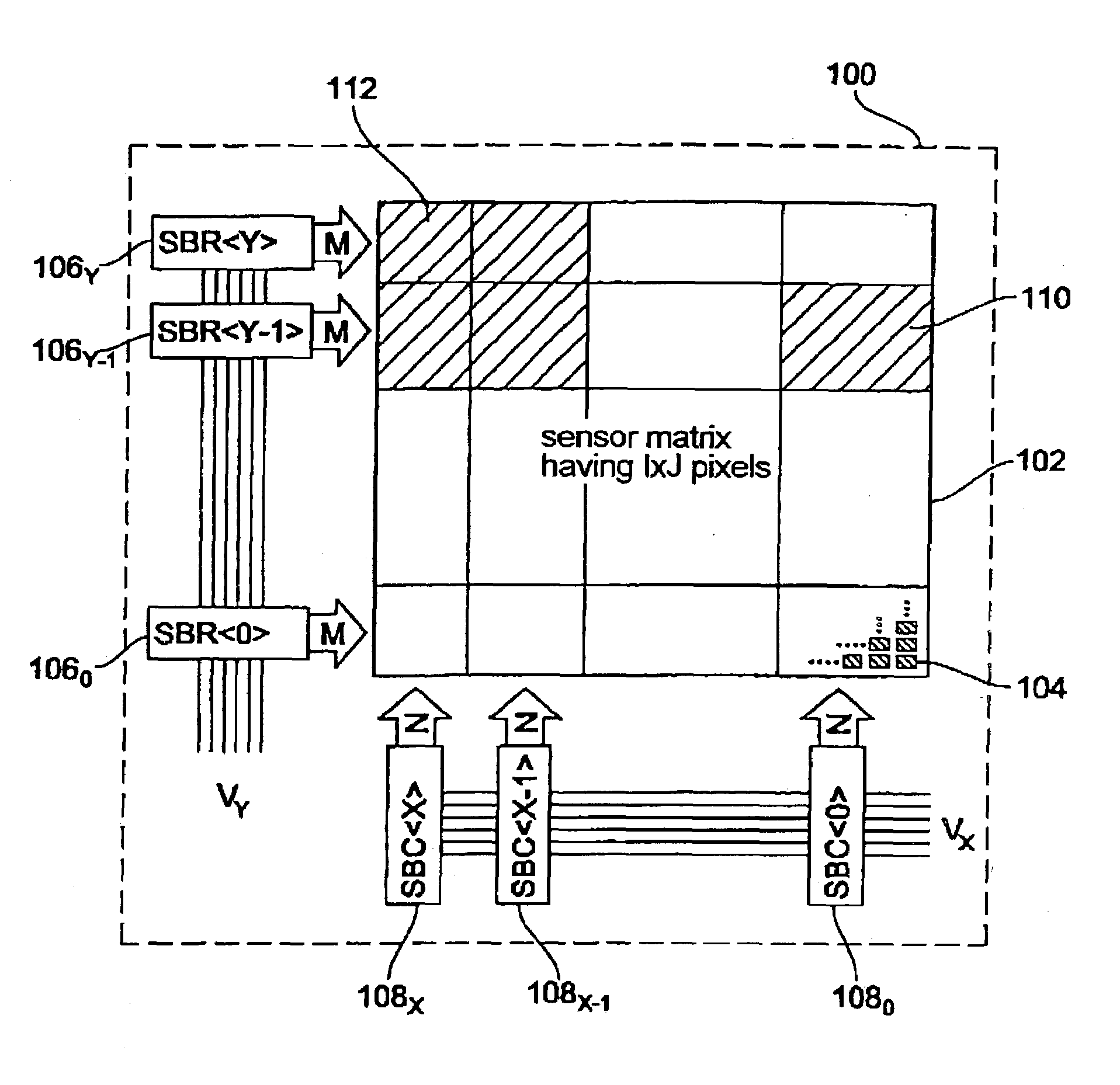
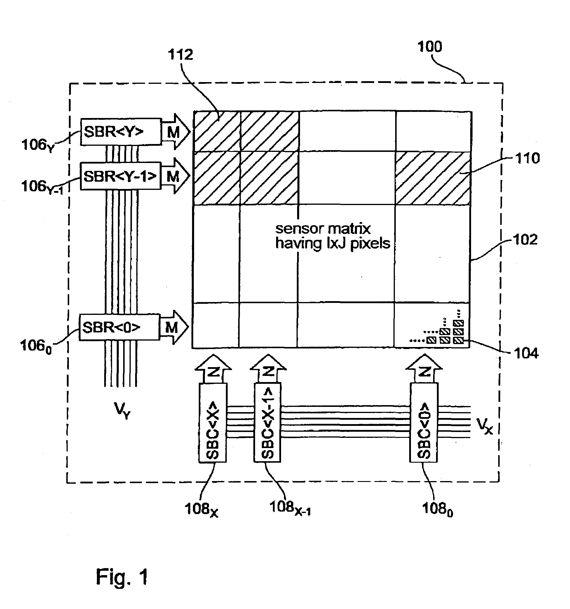
[0036]An image sensor 100 is schematically illustrated in FIG. 1. The image sensor 100 includes a sensor matrix 102 including a plurality of image sensor elements 104, of which, for reasons of clarity, only a few are illustrated in FIG. 1. The sensor matrix 102 basically has the same architecture as a conventional sensor matrix, as has been described, for example, referring to FIG. 7. The image sensor elements 104 (pixels) of the sensor matrix 102 are arranged in I rows and J columns, wherein I, J≧1. In the context of the present invention, driving the individual image sensor elements 104 is of interest so that, for reasons of clarity, the readout rows are not illustrated in FIG. 1.

[0037]In the embodiment shown in FIG. 1, a plurality of row branch blocks (SBR to SBR ) 106o to 106Y are arranged which are connected in series to one another via a plurality of driving lines VY. As is illustrated by the arrows associated with the individual row branch blocks 106o to 106Y, a predetermine...


PUM


Abstract

A device for reading out image data of a sub-range of an image captured by an image sensor is described, the image sensor including a plurality of image sensor elements which can be read out by an activation signal sequentially appliable to same according to a predetermined clock signal, wherein the image sensor elements outputting the image data for the sub-range can be determined by means of an activation pattern. The device comprises a plurality of branch blocks connected in series storing the activation pattern, wherein each of the branch blocks, depending on the activation pattern, applies the activation signal received to one or several image sensor elements associated with a branch block or passes same on to a subsequent branch block or a terminating element. The activation pattern is stored in the branch blocks substantially simultaneously to the activation signal. No delay or latency times, respectively, occur in the sensor readout.

Description

BACKGROUND OF THE INVENTION[0001]1. Field of the Invention[0002]The present invention relates to a method and a device for reading out image data of a sub-range of an image, and to an image sensor including such a device. More precisely, the present invention relates to a method and a device for reading out image data of a sub-range of an image which is detected by an image sensor including a plurality of image sensor elements which can be read out by means of an activation signal sequentially appliable to the image sensor elements according to a predetermined clock signal.[0003]2. Description of Prior Art[0004]Modern industrial and consumer image capturing systems require evermore special image capturing algorithms and image processing algorithms designed for the respective application, wherein it is desirable in some cases to read out sub-ranges within an image with, compared to the usual image rate, multiple speed. Examples of application for this are:[0005]inspection and arrange...

Claims


Application Information

Patent Timeline
IPC IPC(8): H04N3/14H04N5/345H04N5/374H04N5/376
CPCH04N3/1562H04N25/44H04N25/767H04N25/745
Inventor SCHREY, OLAFSCHANZ, MICHAELBROCKHERDE, WERNERHOSTICKA, BEDRICH
Owner INTERDIGITAL CE PATENT HLDG
Why Eureka
Try Eureka