Method for integrated load balancing among peer servers

a peer server and load balancing technology, applied in the field of computer networks and servers, can solve the problems of single point of failure high cost of using the same type of load balancing box for newer generation of servers, and all servers connected to it can lose connectivity to the external network or network

Active Publication Date: 2007-10-16
VALTRUS INNOVATIONS LTD +1
View PDF16 Cites 71 Cited by
  • Summary
  • Abstract
  • Description
  • Claims
  • Application Information

AI Technical Summary

Benefits of technology

[0009]A system for balancing external network loads among a group of computer servers includes a load balancing module attached to or integrated within each server. Each module includes a plurality of network ports. One or more master modules have network ports connected to external networks. All modules have network ports coupled to network ports of other modules to form an internal network through which each module communicates information concerning itself and its server to other modules and through which network messages may be routed to servers in the group.

Problems solved by technology

More expensive and modem load balancing boxes interact with special software agents loaded on servers to collect rudimentary resource utilization information from the servers and use the information as feedback to distribute the loads.
Therefore, using the same type of load balancer boxes for newer generations of servers is expensive, since a load balancer box can cost thousands or tens of thousands of dollars.
In addition, the load balancing box represents a single point of failure.
That is, if the box fails, all servers connected to it can lose connectivity to the external network or networks.
This makes the cost problem even worse.
In this configuration, if one board fails, the boards farther along the chain lose their connection to the network.

Method used


Image

  • Method for integrated load balancing among peer servers
  • Method for integrated load balancing among peer servers
  • Method for integrated load balancing among peer servers

Examples


Embodiment Construction

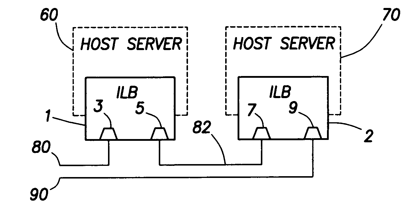
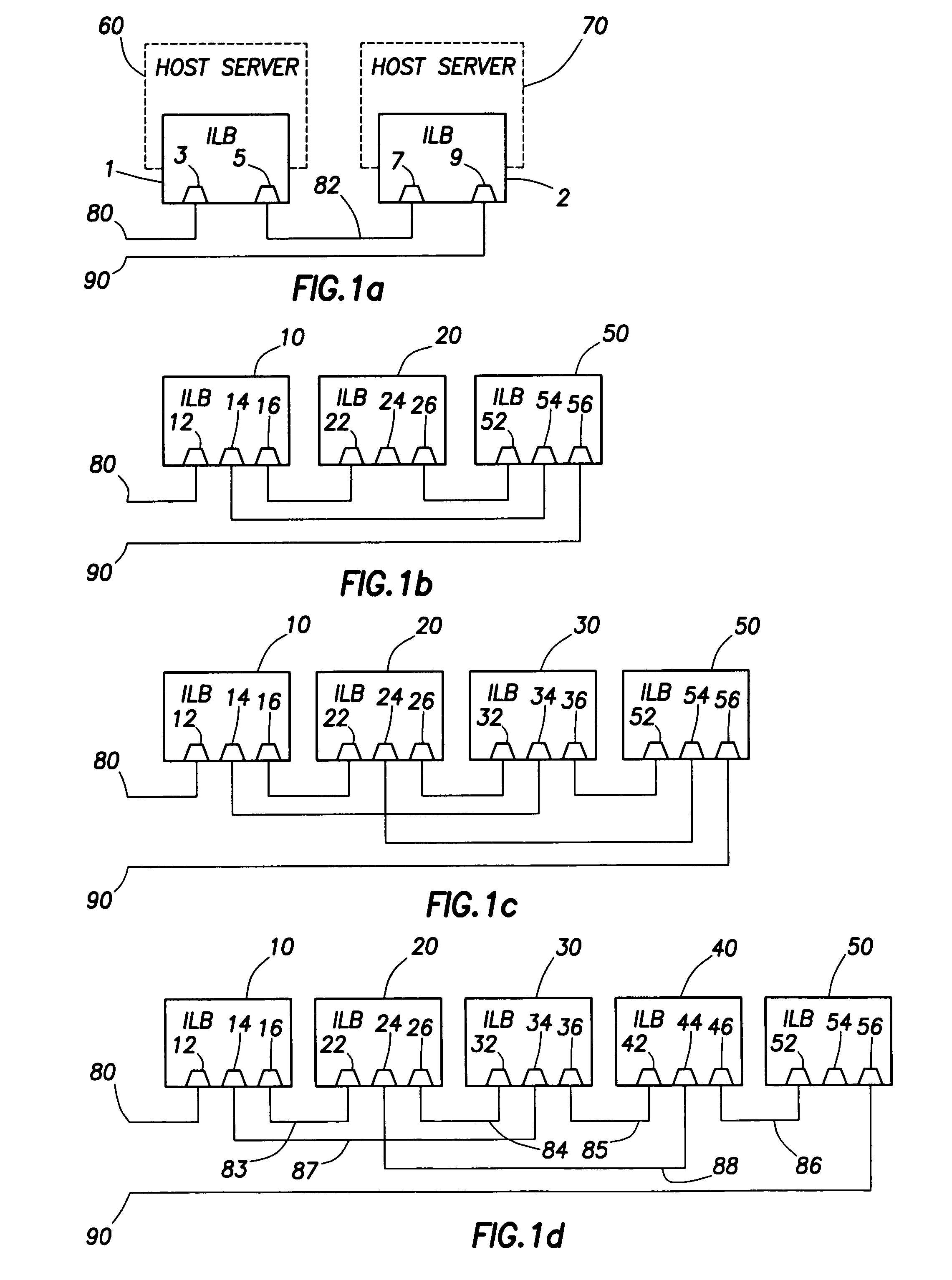
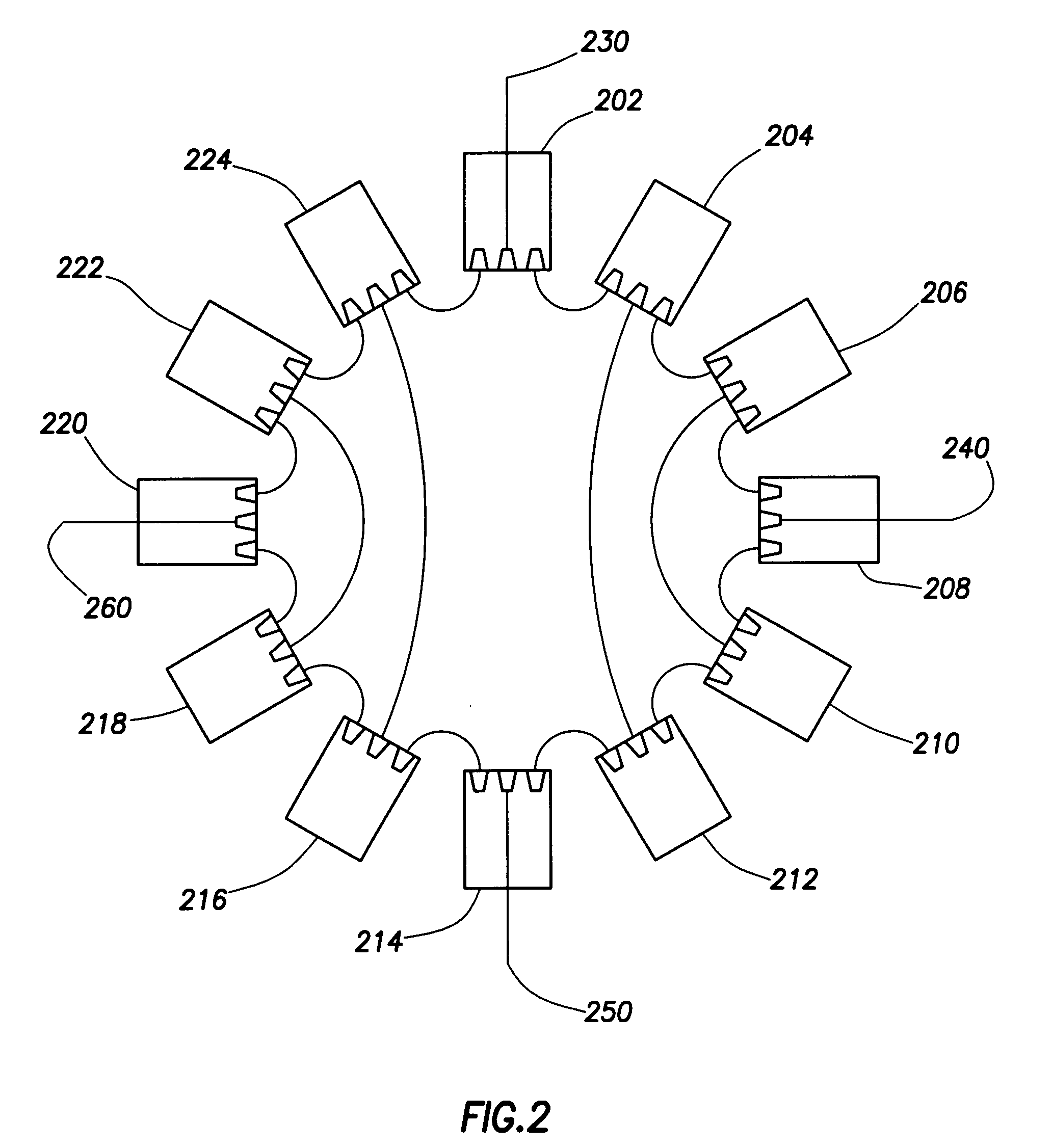
[0017]The present invention relates to a method for connecting multiple computer servers to each other and to an external network or networks in an efficient, reliable, and cost-effective manner. The invention enables the servers to share information with their peers on data traffic volume and capacity and thus to efficiently balance loads among themselves. Load balancing involves either distributing traffic to the servers so that all servers have approximately equal ratios of traffic volume to traffic handling capacity, or when traffic volume is low, reducing or turning off power to some servers while others handle the traffic. Multiple data paths are provided among the servers and to any external networks. This redundancy of data paths allows connectivity to be maintained if a network connection is lost or if a server fails or is disconnected. Balancing of loads, redundancy of connections, and assurance of connectivity to other servers during failure or disconnection of one or mor...


PUM


Abstract

A system for balancing network loads among a group of computer servers. A load balancing module is provided for each server and includes multiple network ports for receiving network traffic and coupling messages to its server or to another module. The interconnect map for the modules is automatically determined by a topology discovery system and maintained by a topology update system. Each module monitors the loading and health of its server and provides this information to the other modules. One or more master modules are directly connected to an external network and route received traffic to their own servers and other servers through other modules or a networking switch based on a priority system. The priority system may be based on dynamic conditions of server capacities and current loading.

Description

CROSS-REFERENCE TO RELATED APPLICATIONS[0001]Not applicableSTATEMENT REGARDING FEDERALLY SPONSORED RESEARCH OR DEVELOPMENT[0002]Not applicable.BACKGROUND OF THE INVENTION[0003]1. Field of the Invention[0004]The present invention generally relates to computer networks and servers and more particularly to a method for balancing network loads among multiple servers.[0005]2. Background of the Invention[0006]It is often desirable to connect multiple server computers to one or more external networks. Balancing of data traffic loads is often desirable when multiple servers are interconnected. Load balancing involves either distributing traffic to the servers so that all servers have approximately equal ratios of traffic volume to traffic handling capacity or, when traffic volume is low, reducing power to some servers while others handle the traffic. Traditionally, load balancing of a number of servers is achieved by connecting them to a dedicated, external load balancer box. Traditionally,...

Claims


Application Information

Patent Timeline
Patent Type & Authority Patents(United States)
IPC IPC(8): G06F15/173H04L29/06H04L29/08
CPCH04L67/1008H04L67/1029H04L67/1012H04L67/1002H04L67/101H04L67/1001
Inventor LEIGH, KEVIN B.
Owner VALTRUS INNOVATIONS LTD
Why Eureka
Try Eureka