

Blade holder having displacement-dependent spring force compensation
- Summary
- Abstract
- Description
- Claims
- Application Information
AI Technical Summary
Benefits of technology
Problems solved by technology
Method used
Image

Examples
Embodiment Construction
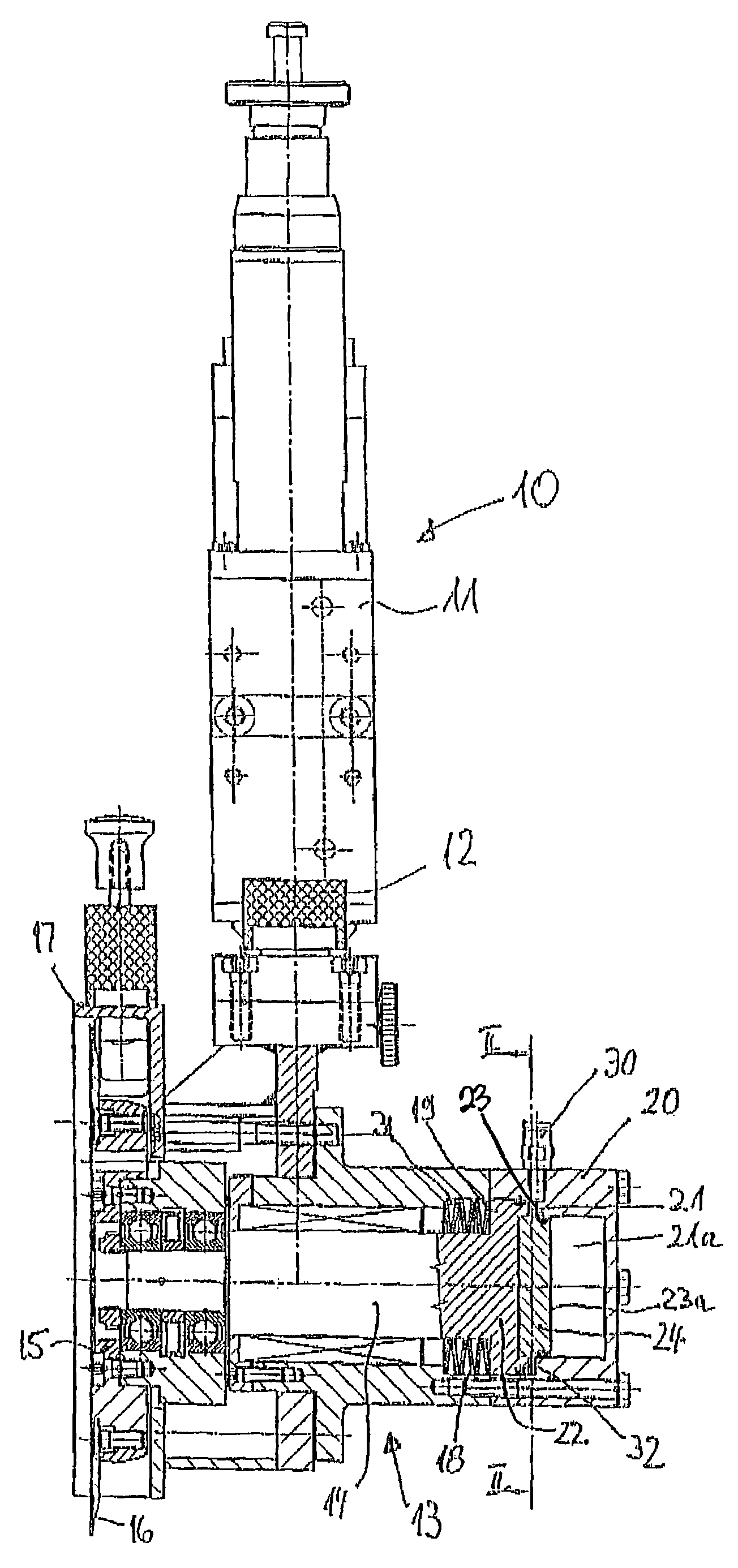
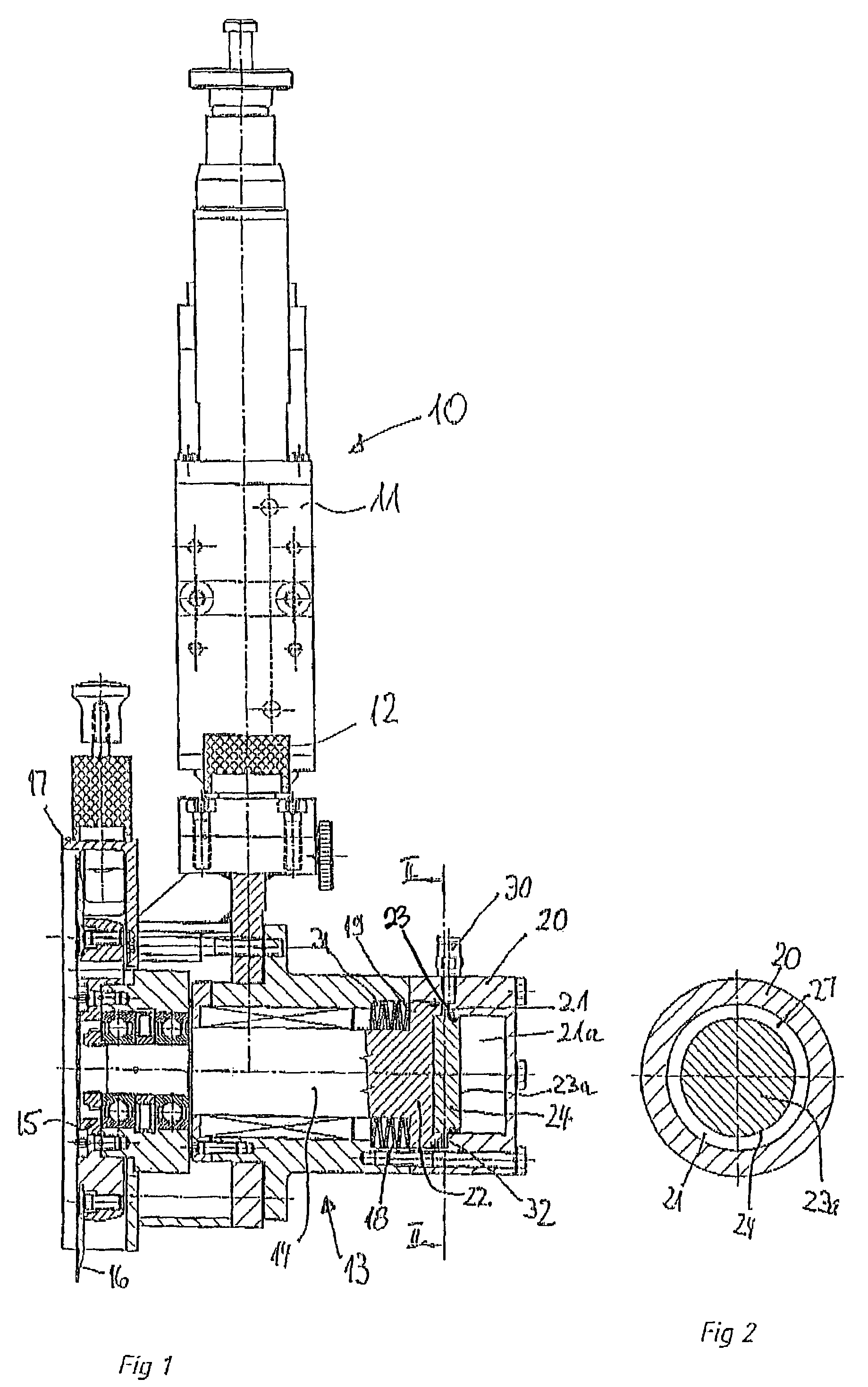
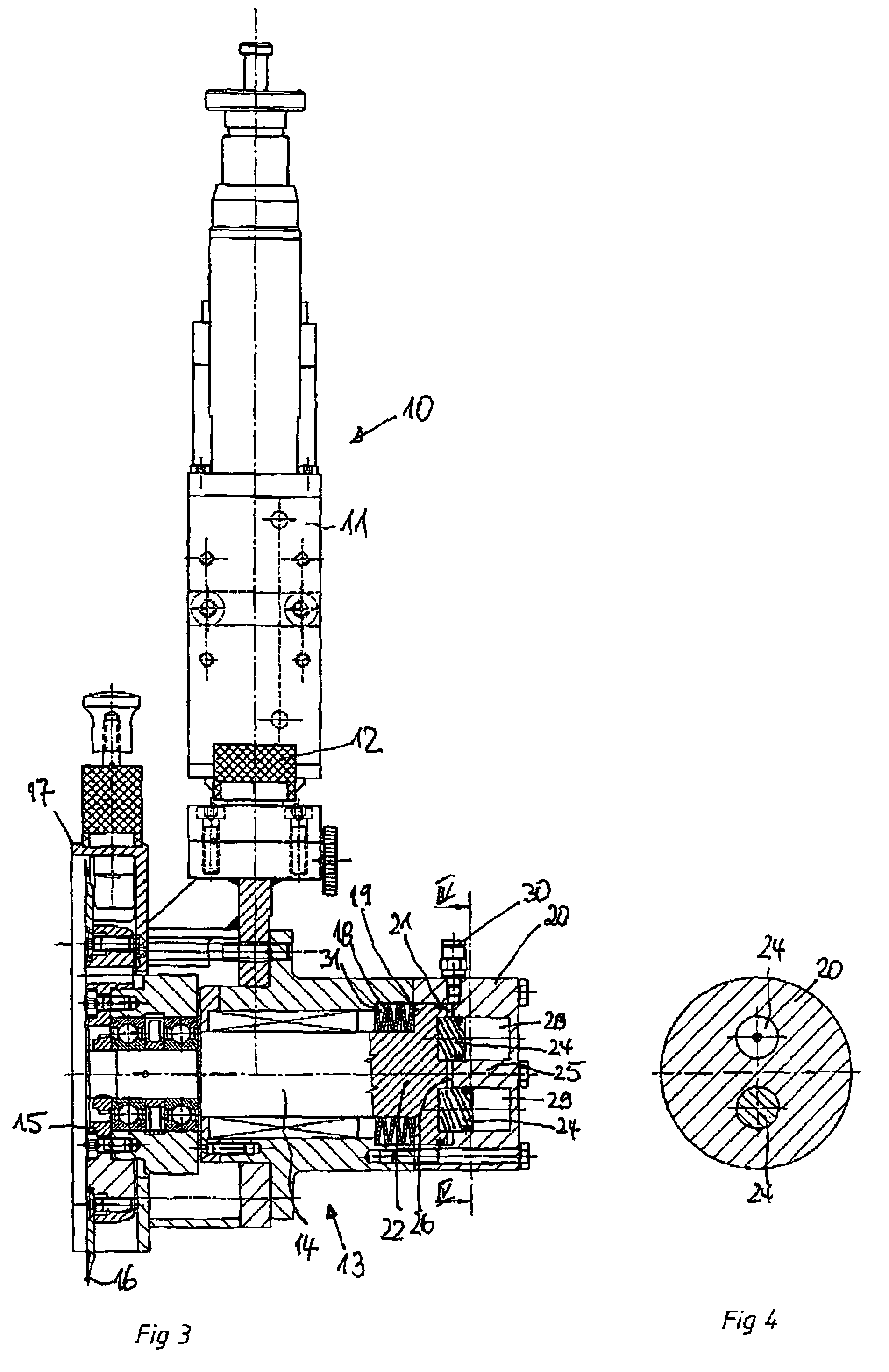
[0021]With the blade holder 10 shown in FIG. 1, disposed at the end of a lowering piston rod 12 having a raising and lowering device 11, which is not part of the subject matter of this invention and furthermore belongs to the state of the art pursuant to DE 38 41 576 C1, is a cutter or blade head 13 in which an adjustment piston rod 14 is displaceably disposed transverse to the axis of the lowering piston rod 12. Mounted on the associated end of the adjustment piston rod 14 is a blade carrier 15 on which is held a circular blade 16. In the ready position of the circular blade 16 illustrated in the drawing, the circular blade is surrounded by a hand guard 17.
[0022]As not further illustrated, by shifting the adjustment piston rod 14 to the left in the illustrated drawing, the circular blade 16 can be brought into a non-illustrated cutting position in which it cooperates with a similarly not-illustrated lower blade.
[0023]To carry out this adjustment movement, disposed in the blade head...
PUM
| Property | Measurement | Unit |
|---|---|---|
| Diameter | aaaaa | aaaaa |
| Area | aaaaa | aaaaa |
| Dimension | aaaaa | aaaaa |
Abstract
Description
Claims
Application Information