Harsh environment connector including end cap and latching features and associated methods

a technology of end caps and latching features, applied in the direction of coupling device details, coupling device connections, electric discharge lamps, etc., can solve the problems of limited movement types of robotic devices, and achieve the effect of reliable service and convenient manufacturing

Inactive Publication Date: 2007-10-23
TELEDYNE INSTR INC
View PDF20 Cites 24 Cited by
  • Summary
  • Abstract
  • Description
  • Claims
  • Application Information

AI Technical Summary

Benefits of technology

[0007]In view of the foregoing background, it is therefore an object of the invention to provide a connector that is more readily manufactured and still reliable in service.
[0009]The end cap and adjacent portions of the second shell may comprise respective mating portions to provide a snap fit engagement therebetween. For example, the end cap may comprise an enlarged diameter flange and the second shell may have a recess for receiving the enlarged diameter flange therein. The snap fit engagement may provide for more efficient assembly during manufacturing.

Problems solved by technology

A submersible robotic device may also typically be used to mate the wet-mateable cable connector portions, and such a robotic device may be limited in the types of movements and forces it is capable of generating.

Method used


Image

  • Harsh environment connector including end cap and latching features and associated methods
  • Harsh environment connector including end cap and latching features and associated methods
  • Harsh environment connector including end cap and latching features and associated methods

Examples


Embodiment Construction

[0032]The invention will now be described more fully hereinafter with reference to the accompanying drawings, in which preferred embodiments of the invention are shown. This invention may, however, be embodied in many different forms and should not be construed as limited to the embodiments set forth herein. Rather, these embodiments are provided so that this disclosure will be thorough and complete, and will fully convey the scope of the invention to those skilled in the art. Like numbers refer to like elements throughout.

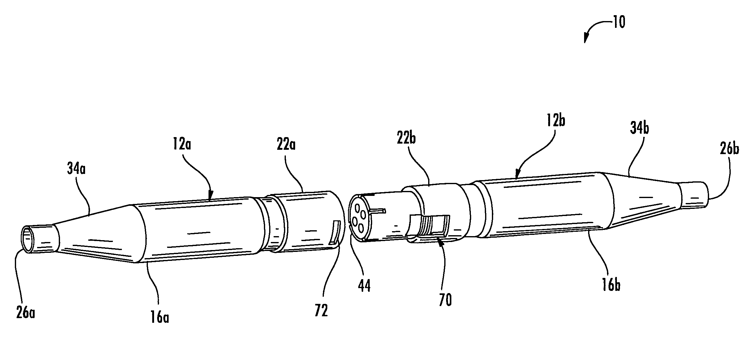
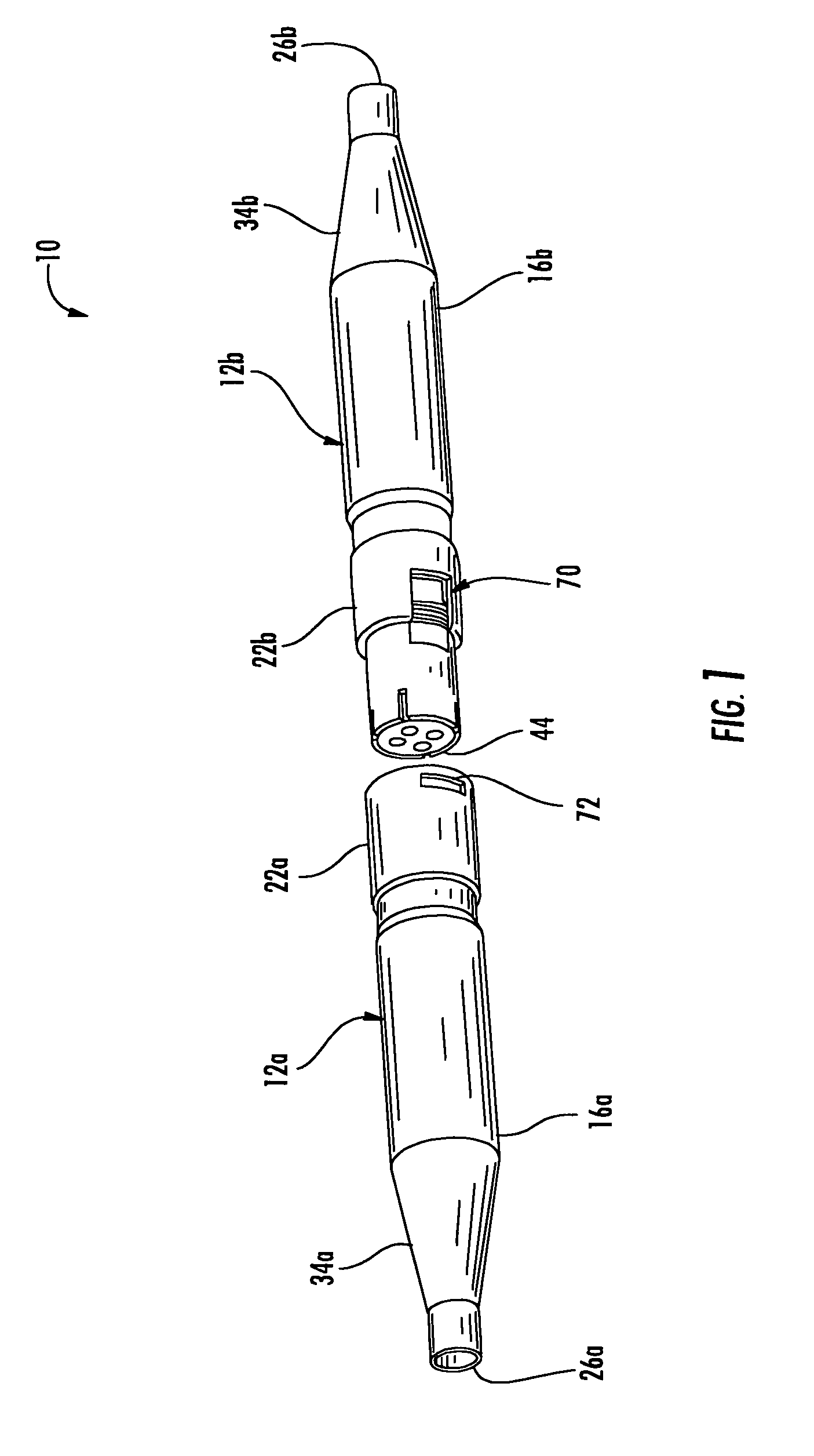
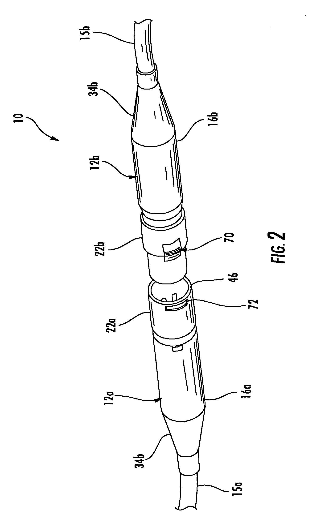
[0033]Referring initially to FIGS. 1-6, a connector 10 and its sealing apparatus for harsh environments in accordance with the invention is now described. The connector 10 illustratively comprises first and second connector portions 12a, 12b being movable between unmated and mated positions as will be appreciated by those of skill in the art. Each connector portion 12a, 12b includes an elastomeric inner seal 14a, 14b and an elastomeric outer seal 16a, 16b surround...


PUM


Abstract

A connector, such as for harsh environments, may include first and second connector portions being movable between unmated and mated positions. The first connector portion may include a first base, at least one male contact carried by the first base and extending outwardly therefrom, and a first shell carried by the first base and surrounding the at least one male contact. The second connector portion may include a second base, at least one female contact carried by the second base and extending outwardly therefrom, and a bladder carried by the second base and surrounding the at least one female contact. The second connector portion may further include an end cap having at least one passageway therein for retaining and aligning end portions of the bladder opposite the second base, and a second shell carried by the second base and surrounding the bladder and the end cap. The end cap and adjacent portions of the second shell may include respective mating portions to provide a snap fit engagement therebetween. The end cap may include an integrally formed monolithic body. A manual release latch and corresponding latch opening may be provided in the connector shells.

Description

FIELD OF THE INVENTION[0001]The invention relates to the field of cable connectors, and, more particularly, to cable connectors and related methods such as for harsh environments.BACKGROUND OF THE INVENTION[0002]Underwater cables are commonly used to carry electrical power and / or telecommunications traffic. There is also typically a need to make connections between adjacent cable ends, or between a cable end and associated equipment, for example. Accordingly, there are also cable connectors for such harsh or underwater, high pressure environments. Such cable connectors not only have to operate under extreme conditions, but for some applications they may need to be mateable while submerged, that is, wet-mateable. A submersible robotic device may also typically be used to mate the wet-mateable cable connector portions, and such a robotic device may be limited in the types of movements and forces it is capable of generating.[0003]The assignee of the present invention, Ocean Design, Inc...

Claims


Application Information

Patent Timeline
Patent Type & Authority Patents(United States)
IPC IPC(8): H01R13/627
CPCH01R13/6272H01R13/521H01R13/5205H01R13/64
Inventor CAIRNS, JAMES L.BARLOW, STEWART M.
Owner TELEDYNE INSTR INC
Why Eureka
Try Eureka