Spring-clamp style contact for PCB to terminate solar panel tabbing

Active Publication Date: 2007-10-23
TE CONNECTIVITY CORP
View PDF17 Cites 26 Cited by
  • Summary
  • Abstract
  • Description
  • Claims
  • Application Information

AI Technical Summary

Benefits of technology

[0009]One advantage of the present invention is the lower manufacturing costs, and no maintenance costs for the system.
[0010]Another advantage of the present invention is improved junction box performance with improved cooling means of the electrical components.
[0011]Yet another advantage of the present invention is improved replaceability functionality.
[00

Problems solved by technology

Most commonly, junction boxes employ electronic rails to which the electronics are soldered thereon creating a semi permanent connection that makes replacement of the parts difficult.
Another issue with the current systems is the fragility of the electronics disposed in the junction boxes.
The electronic components are unable to sustain the forces of inserting wire tabbing into the connections within the junction box.
Often times the electronics are damaged

Method used


Image

  • Spring-clamp style contact for PCB to terminate solar panel tabbing
  • Spring-clamp style contact for PCB to terminate solar panel tabbing
  • Spring-clamp style contact for PCB to terminate solar panel tabbing

Examples


Example

[0031]Wherever possible, the same reference numbers will be used throughout the drawings to refer to the same or like parts.

DETAILED DESCRIPTION OF THE INVENTION

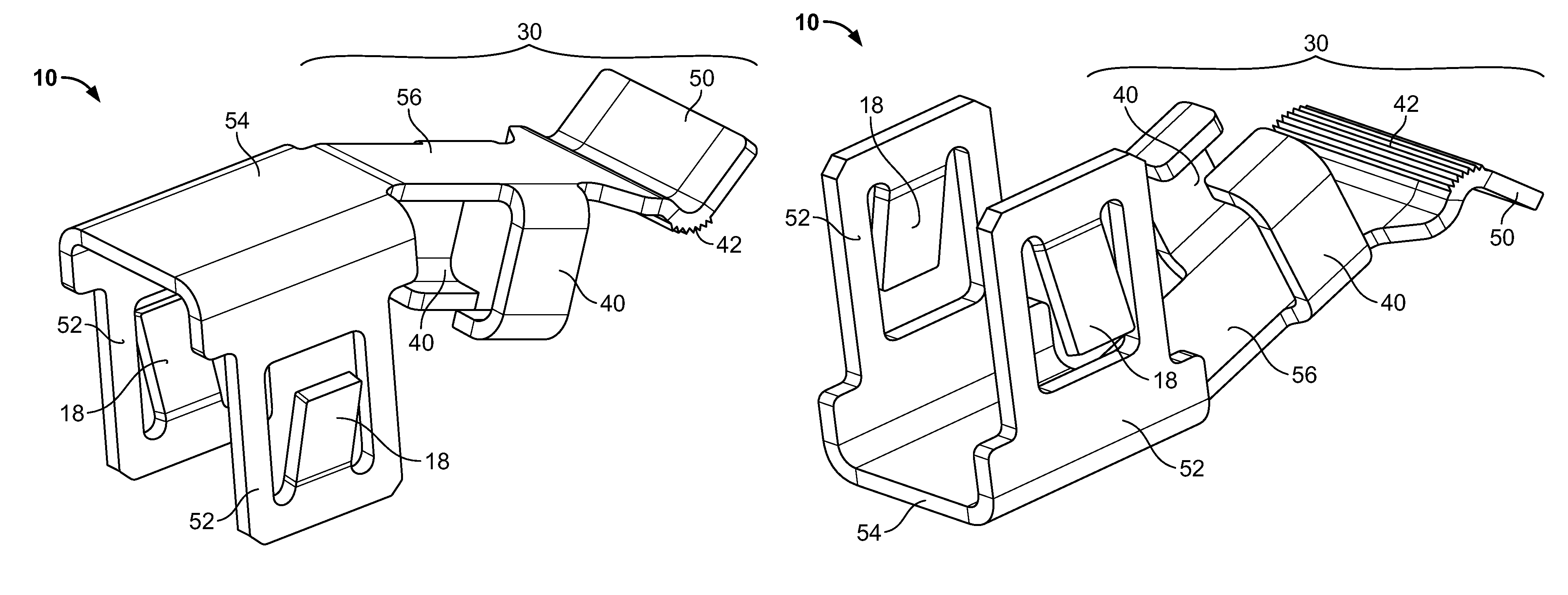
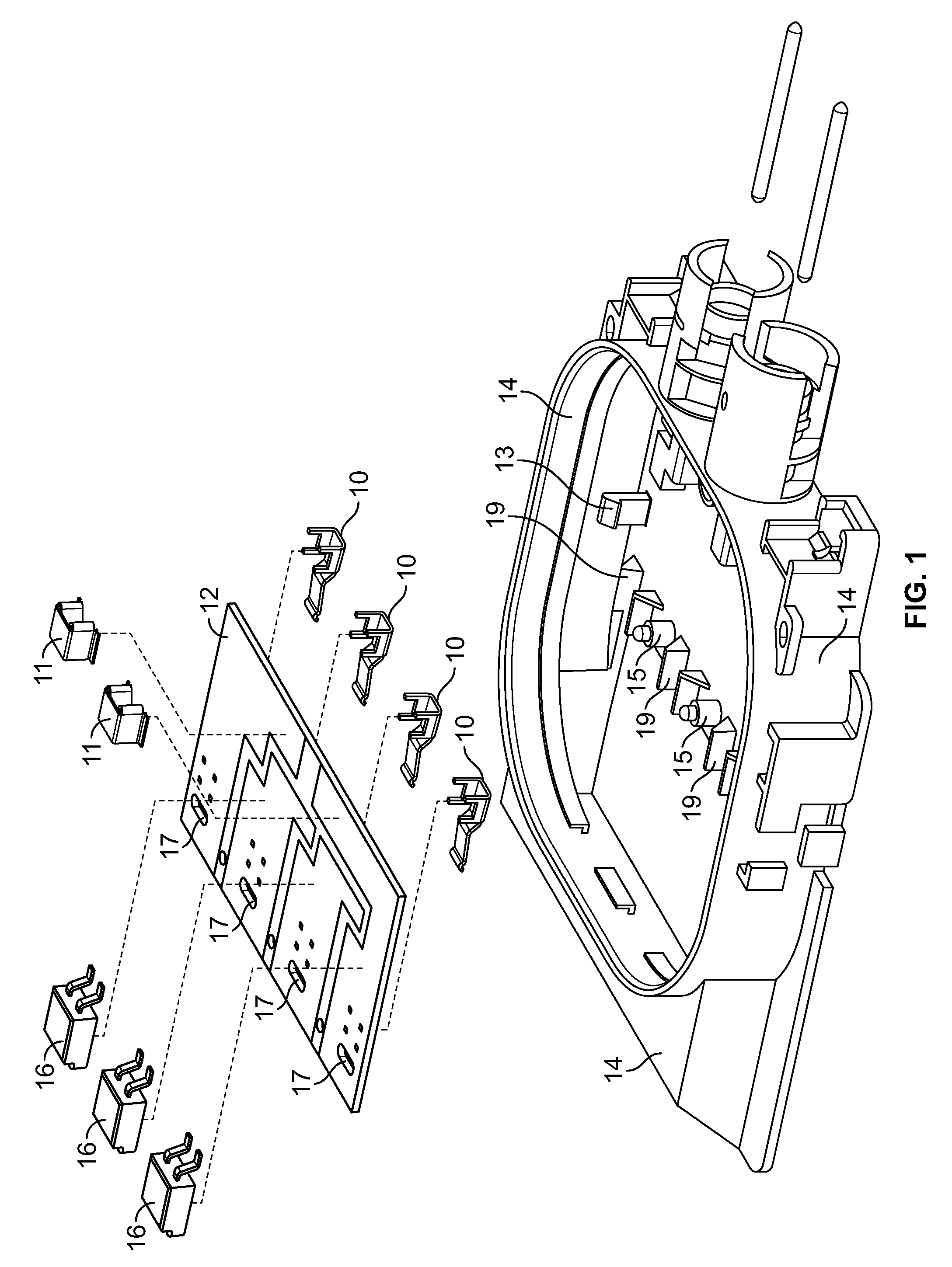
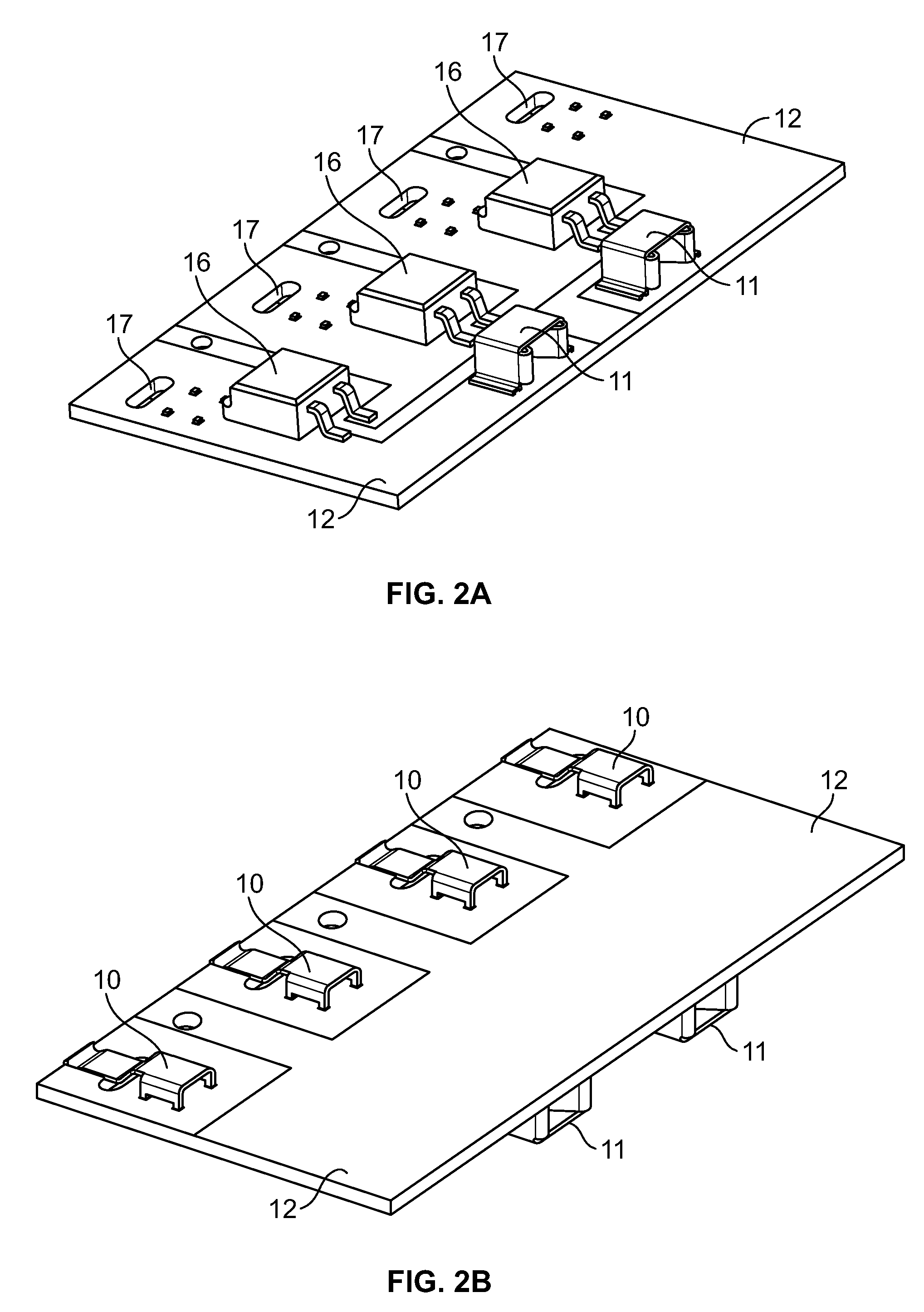
[0032]The present invention is directed to a printed circuit board with a spring clip mount assembly that meets the temperature requirements of the IEC 61215, and reduces the normal forces sustained by the circuit board and components during insertion of the wire tabbing into the junction box. FIG. 1 is an exploded view of the present invention showing the power interface contacts 11 that direct power to the PV power grid (not shown), the diodes 16 that are part of the electric circuitry on the printed circuit board 12, the printed circuit board 12 and spring clips 10 that receive wire tabbing into the junction box 14 where power from the solar cells enters. The junction box 14 can be constructed of a substantially rigid non-conductive material suitable to receive a printed circuit board 12, such as an ABS plastic or other s...


PUM


Abstract

A spring clip modular assembly for a printed circuit board that has a solderless connection with a junction box. The assembly allows for easier and more efficient removal and replacement of the printed circuit board and electrical components while meeting the IEC 61215 second edition temperature standards. In addition, the spring clip is configured to reduce the amount of normal force applied to the printed circuit board when wire tabbing is inserted into the clips.

Description

BACKGROUND OF THE INVENTION[0001]The present invention is directed to an improved system and method for securing electronics in a junction box while meeting industry temperature standards. More specifically, the present invention is directed to a printed circuit board that is secured in a junction box with a solderless connection with spring clips mounted thereon.[0002]Most commonly, junction boxes employ electronic rails to which the electronics are soldered thereon creating a semi permanent connection that makes replacement of the parts difficult. Another issue with the current systems is the fragility of the electronics disposed in the junction boxes. The electronic components are unable to sustain the forces of inserting wire tabbing into the connections within the junction box. Often times the electronics are damaged or the solder connections are broken from the force of repeatedly inserting and removing the wire tabbing into the junction box. In addition, the current systems c...

Claims


Application Information

Patent Timeline
IPC IPC(8): H01R11/20
CPCH01R4/4809H01R4/5075H01R13/6658H01R13/6641
Inventor DAILY, CHRISTOPHER GDUESTERHOEFT, SCOTT
Owner TE CONNECTIVITY CORP
Why Eureka
Try Eureka