Liquid crystal display unit having a field sequential driven backlight unit

Active Publication Date: 2007-10-23
LG DISPLAY CO LTD
View PDF7 Cites 27 Cited by
  • Summary
  • Abstract
  • Description
  • Claims
  • Application Information

AI Technical Summary

Benefits of technology

[0078]An object of the present invention is to provide a backlight unit of a display device and a liquid crystal display device using the same in which light leakage to a neighboring reg

Problems solved by technology

CRT (Cathode Ray tube), one of general display devices, is mainly being used as a monitor for television (TV), measuring machine, information terminal, etc., but fails to cope positively with requests for miniaturization and lightness of electronics products due to the size and weight of the CRT itself.
Thus, CRT has a limitation in decreasing the weight and volume, which is contrary to a current tendency of the miniaturization and lightness of the electronic products.
First, the transmittance of the light of the color filter of a general LCD device is less than 33% at most, which corresponds to a large light loss. To enhance the brightness by compensating for the light loss due to the color filter, the backlight should be made brighter. However, such a solution causes increase in the power consumption by the backlight and thus by the LCD device.
Second, since the color filter of a general LCD device is very expensive compared with the other materials of the LCD device, the color filter raises the production cost of the LCD device.
This field sequential method was suggested in 1960s, but it was very difficult to implement it since the technologies for a liquid crystal mode having a high speed response time and a light source meeting the high speed liquid crystal mode have to follow the field sequential method.
Further, the general LCD devic

Method used


Image

  • Liquid crystal display unit having a field sequential driven backlight unit
  • Liquid crystal display unit having a field sequential driven backlight unit
  • Liquid crystal display unit having a field sequential driven backlight unit

Examples


first embodiment

[0117]According to the invention, a backlight unit for a display device such as an LCD device includes a main light guide plate, a lamp housing configured concave, and auxiliary light guide plates further arranged below both sides of the main light guide plate.

[0118]In the invention, the display area (e.g., corresponding the display area of the LCD device) can be divided into an n number of regions intentionally. In the below, as an example, a four division driving backlight unit in which the light guide plate is divided into four regions will be described.

[0119]FIG. 8A is a top plan view of a backlight unit usable with or in a display device such as an LCD device according to the first embodiment of the present invention, and FIG. 8B is a cross-sectional view taken along the line I-I′ of FIG. 8A.

[0120]As shown in FIGS. 8A and 8B, the backlight unit according to the first embodiment of the present invention is configured to include a main light guide plate 81, which is divided into ...

second embodiment

[0130]According to the invention, a backlight unit for a display device such as an LCD device includes a light guide plate divided into multiple regions corresponding to the number of FS driven regions.

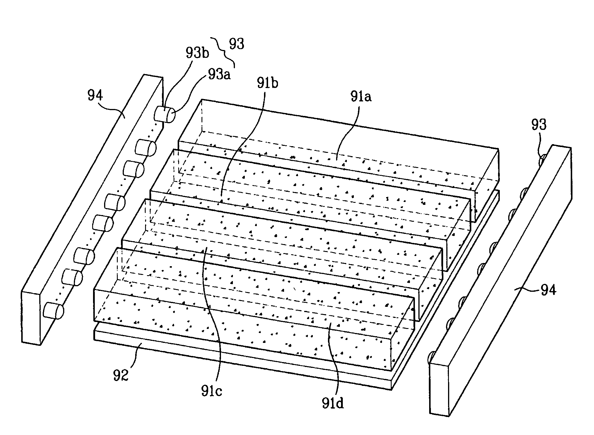
[0131]FIG. 9 is a perspective view of an FS type backlight unit usable with or in an LCD device according to the second embodiment of the present invention, FIG. 10A is a driving top plan view of the backlight unit of FIG. 9, and FIG. 10B is a cross-sectional view taken along the line II-II′ of FIG. 10A.

[0132]In the invention, the display area can be divided into an n number of regions intentionally. In the below, as an example, a four division driving backlight unit in which the light guide plate is divided into four regions will be described.

[0133]As shown in FIG. 9, the backlight unit according to the second embodiment of the present invention is configured to include first to fourth light guide plates 91a, 91b, 91c and 91d, which are divided into four regions to be FS (field seque...

third embodiment

[0140]According to the invention, a backlight unit for a display device such as an LCD device includes two sheets of light guide plates arranged in a stack structure and LED lamps arranged in a zigzag at the side portions of the upper and lower light guide plates.

[0141]FIG. 11 is a perspective view of an FS type backlight unit usable with or in a display device such as an LCD device according to the third embodiment of the present invention, and FIG. 12 is a sectional view illustrating the structure and operation of upper and lower light guide plates of FIG. 11.

[0142]In the invention, the display area can be divided into an n number of regions intentionally. In the below, as an example, a backlight unit in which the light guide plate is divided into four regions will be described.

[0143]As shown in FIG. 11, the backlight unit according to the third embodiment of the present invention is configured to include upper and lower light guide plates 111 and 112, each of which is divided int...


PUM


Abstract

A backlight unit for a display device and a liquid crystal display device using the backlight unit suppresses light leakage to a neighboring region with a display area that is divided and driven by a DDAM (Divided Display Area Method). The backlight unit in one aspect includes a main light guide plate defined by an n number of regions for a field sequential driving, auxiliary light guide plates arranged below edges of the main light guide plate, first and second reflection plates arranged below the main light guide plate and the auxiliary light guide plate, a plurality of light source parts arranged at a predetermined interval at both sides of the auxiliary light guide plate, and a housing configured to enclose a side of the main light guide plate, the auxiliary light guide plate and side and lower portion of the light source parts.

Description

[0001]This application claims the priority benefit of the Korean Patent Application No. P2002-84100 filed on Dec. 26, 2002, which is hereby incorporated by reference.BACKGROUND OF THE INVENTION[0002]1. Field of the Invention[0003]The present invention relates to a backlight unit, and more particularly, to a backlight unit of a display device employing DDAM (Divided Display Area Method) in which a display area is divided into a plurality of regions for operation, among Field Sequential (FS) driving methods, and to a liquid crystal display device using the backlight unit.[0004]2. Discussion of the Related Art[0005]CRT (Cathode Ray tube), one of general display devices, is mainly being used as a monitor for television (TV), measuring machine, information terminal, etc., but fails to cope positively with requests for miniaturization and lightness of electronics products due to the size and weight of the CRT itself.[0006]Thus, CRT has a limitation in decreasing the weight and volume, whi...

Claims


Application Information

Patent Timeline
IPC IPC(8): G02F1/13F21V8/00G02B6/00G02F1/13357
CPCG02B6/0028G02B6/0031G02B6/0076G02B6/0078G02F1/133615G02B6/0068G02B6/0043G02B6/0056G09G3/342G02F2001/133622G02F1/133622G02F1/1335
Inventor YOO, JANG JINWOO, JONG HOON
Owner LG DISPLAY CO LTD
Why Eureka
Try Eureka