
Electric double layer capacitor

a double-layer capacitor and capacitor technology, applied in the direction of electrolytic capacitors, liquid electrolytic capacitors, electrochemical generators, etc., can solve the problems of preventing preventing the interfusal of unnecessary materials from the outside, and maintaining the insulation distance, so as to prevent the interfusal of unnecessary materials, prevent the trouble of an electric double-layer capacitor, and prevent the effect of leakage of an electrolytic solution

Inactive Publication Date: 2007-10-23
AGC INC
View PDF17 Cites 17 Cited by
  • Summary
  • Abstract
  • Description
  • Claims
  • Application Information

AI Technical Summary

Benefits of technology

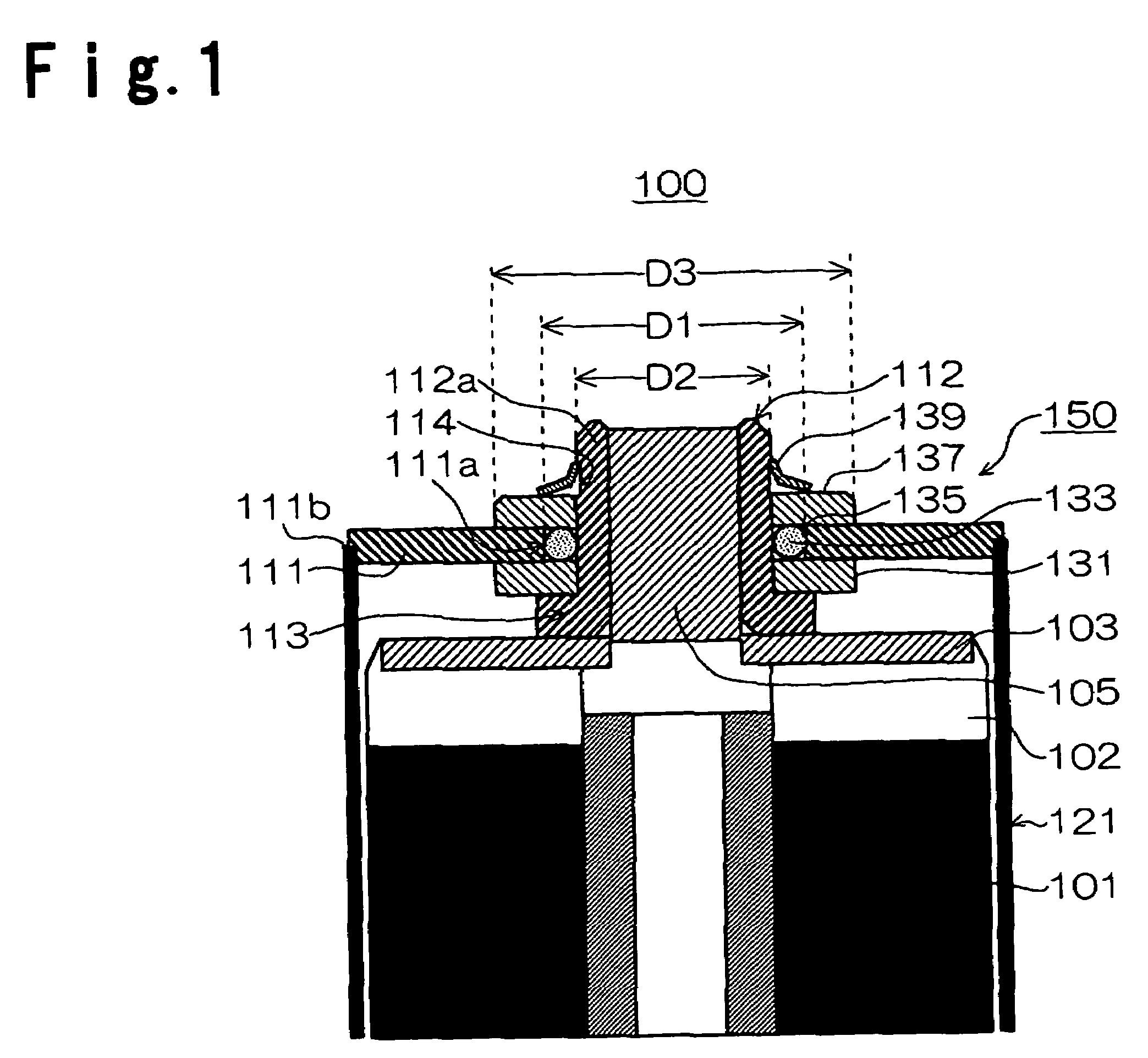
[0043]As described above, according to the present invention, a ring-shaped sealing member is provided in a spacing between an inner face of a through hole perforating a sealing plate and an outer face of a terminal, and a sealing member and insulation members are interposed between the terminal and the sealing plate, whereby it is possible to maintain airtightness between the terminal and the sealing plate and to prevent leakage of an electrolytic solution through a gap between these members. Further, it is also possible to prevent interfusion of unnecessary materials from the outside. Further, since the terminal and the sealing plate are sufficiently insulated, it is possible to prevent short circuit through a liquid or short circuit to the earth due to dew condensation can be prevented. Accordingly, troubles of an electric double layer capacitor can be prevented.
[0044]Further, by use of fixing means, it is possible to press the terminal and a second insulation member against the upper side and to press a first insulation member against the lower side. As a result, it is possible to sufficiently maintain airtightness between the terminal and the sealing plate. For this reason, the sealing structure of the present invention can be suitably used as a sealing structure for a non-aqueous type electrolytic solution type electric double layer capacitor in which a moisture in an element or a gas due to decomposition of the electrolytic solution, is generated at a time of applying high voltage.BRIEF EXPLANATION OF THE DRAWINGS
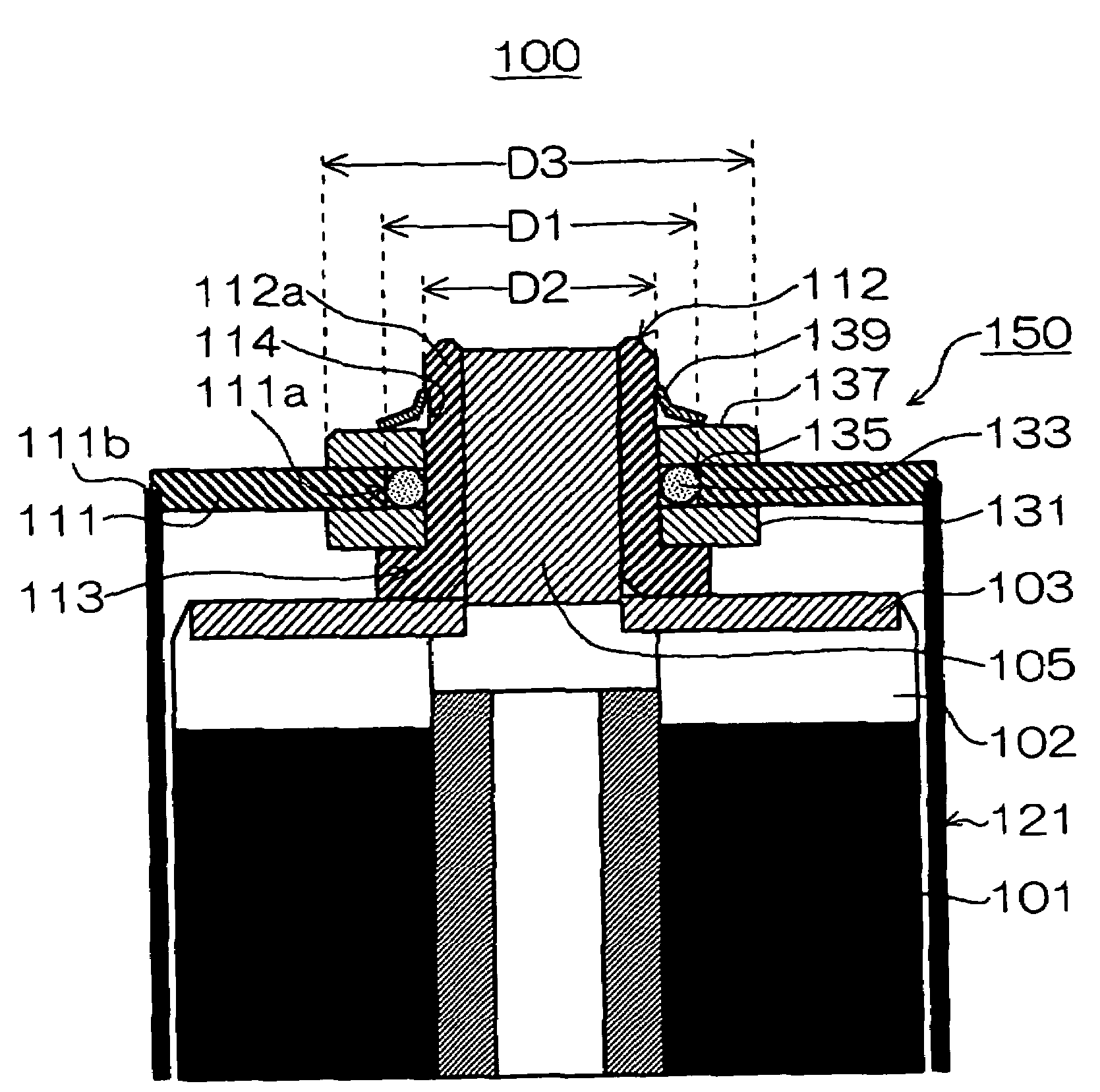
[0045]FIG. 1: A cross sectional view of an electric double layer capacitor of a first embodiment of the present invention.
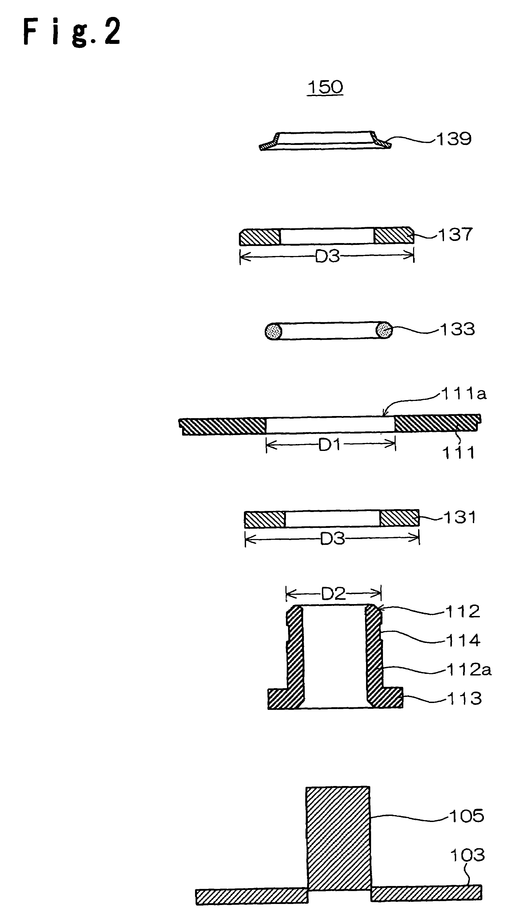
[0046]FIG. 2: An exploded view of the terminal portion of FIG. 1.
[0047]FIG. 3: Another example of an electric double layer capacitor of the first embodiment of the present invention.
[0048]FIG. 4: An exploded view of the terminal portion of FIG. 3.

Problems solved by technology

Additionally, there has been a risk that unnecessary materials are interfused from the outside.
However, in such a terminal portion 10B, it is not possible to maintain the insulation distance between the sealing plate 31 and the outer casing 21, and there has been a risk that short circuit through a liquid or short circuit to the earth is occurred by a dew condensation formed on the one-piece type cap 35 or the outer casing 21.

Method used


Image

  • Electric double layer capacitor
  • Electric double layer capacitor
  • Electric double layer capacitor

Examples


example

[0126]The most suitable example of the above electric double layer capacitors 100, 200 and 300 will be described. The material of the outer casing 121 is not particularly limited, and it is preferably, for example, a metal material or a resin material. Further, the material of the sealing plate 111 is also not particularly limited, and it is preferably, for example, a metal material or a resin material.

[0127]Further, the material of the terminal 112 is the most preferably aluminum, an aluminum alloy or a stainless steel so as to reduce the resistance of the terminal 112 itself. The material of the electric collection member 105 is also the most preferably aluminum, an aluminum alloy or a stainless steel to reduce the resistance of the electric collection member itself and since the same material as the electric collector plate 103 is preferred for e.g. bonding with the electric collector plate 103.

[0128]Further, the material of the lower-insulation ring 131 is not particularly limit...


PUM

PropertyMeasurementUnit
thicknessaaaaaaaaaa
electricaaaaaaaaaa
electric energyaaaaaaaaaa

Abstract

An electric double layer capacitor capable of preventing leakage of an electrolytic solution from the inside and interfusion of unnecessary material from the outside, and capable of forming insulation between a terminal and an outer casing, is provided.A lower-insulation ring 131 is fit into a terminal 112 until the lower-insulation ring comes in the upper side of a flange portion 113. Then, the terminal 112 in this state is inserted into a center of the through hole 111a of a sealing plate 111 from the inside of an outer casing 121. Then, an O-ring 133 is press fit into a spacing 135 formed by a cylindrical portion 112a and the through hole 111a. Further, an upper-side insulation ring 137 is fit to the upper side of this press fit O-ring 133. Then, a setting spring 139 is attached to the terminal 112 so as to press down the upper-side insulation ring 137.

Description

CROSS REFERENCE TO RELATED APPLICATIONS[0001]This application claims priority under 35 U.S.C. §371 to PCT / JP2004 / 015521, filed Oct. 20, 2004, and is based upon and claims the benefits of priority from the prior Japanese Patent Application No. 2003-360126, filed on Oct. 21, 2003, both of which are hereby incorporated by reference in their entirety.TECHNICAL FIELD[0002]The present invention relates to an electric double layer capacitor, in particular, to an electric double layer capacitor capable of preventing leakage of an electrolytic solution from the inside and interfusion of unnecessary materials from the outside, and capable of forming isolation between a terminal portion and the outer casing.BACKGROUND ART[0003]An electric double layer capacitor has a terminal portion for conducting inputting and outputting of an electric energy between an element assembly in the inside, and the outside. As the terminal portion, a terminal portion 10A of mold type has been known.[0004]FIG. 6 sh...

Claims


Application Information

Patent Timeline
Patent Type & Authority Patents(United States)
IPC IPC(8): H01G9/00H01G9/10H01G11/80H01G11/82
CPCH01G9/016H01G9/10H01G11/82H01G11/80Y10T29/417Y02E60/13H01G11/74
Inventor HOZUMI, YOSHIHIROIKEDA, KATSUJI
Owner AGC INC
Learn More