Engine air intake apparatus

a technology for air intake and engine, which is applied in the direction of machines/engines, combustion-air/fuel-air treatment, and separation processes, etc., can solve the problems of large overall noise, increased weight of parts, and inability to meet the reduction in size and weight, so as to reduce the size and weight, reduce the effect of material cost and weight reduction

Inactive Publication Date: 2007-10-30
MITSUBISHI ELECTRIC CORP
View PDF6 Cites 8 Cited by
  • Summary
  • Abstract
  • Description
  • Claims
  • Application Information

AI Technical Summary

Benefits of technology

[0010]The present invention aims to solve the above problems and an object of the present invention is to provide a compact, light-weight engine air intake apparatus enabling engine output during high-speed operation to be improved and also enabling air intake noise during low-speed operation to be reduced by enabling sharing of a passage portion among a plurality of air intake passages.
[0012]According to the present invention, because each of the air intake passages has a passage portion shared with another air intake passage, size reductions and weight reductions are enabled compared to when a plurality of air intake passages are formed independently. With the size reductions and the weight reductions, material costs can be reduced, enabling price reductions to be achieved.
[0013]The valve actuator drives the passage switching valve so as to selectively switch among the plurality of air intake passages so as to configure an intake pathway corresponding to an engine operating state. Thus, by enlarging an aperture area of an air intake pathway during high-speed operation and reducing the aperture area of the air intake pathway during low-speed operation, engine output during high-speed operation can be improved and air intake noise during low-speed operation can be reduced.

Problems solved by technology

In passenger car engines, air intake noise emitted from air intake passage inlet portions accounts for a large share of overall noise during slow running when noise resulting from mechanical operation and vibration of the engine itself, exhaust noise, etc., are comparatively small.
Thus, some problems have been that demand for reductions in mounting space for the air intake apparatus inside engine compartments accompanying demands for increased auxiliary machinery and reductions in size and weight cannot be met, and the weight of parts is increased.

Method used


Image

  • Engine air intake apparatus
  • Engine air intake apparatus
  • Engine air intake apparatus

Examples


embodiment 1

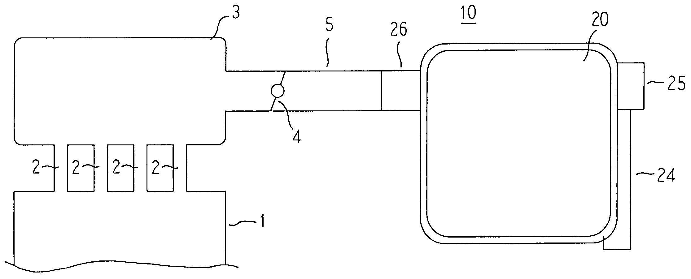
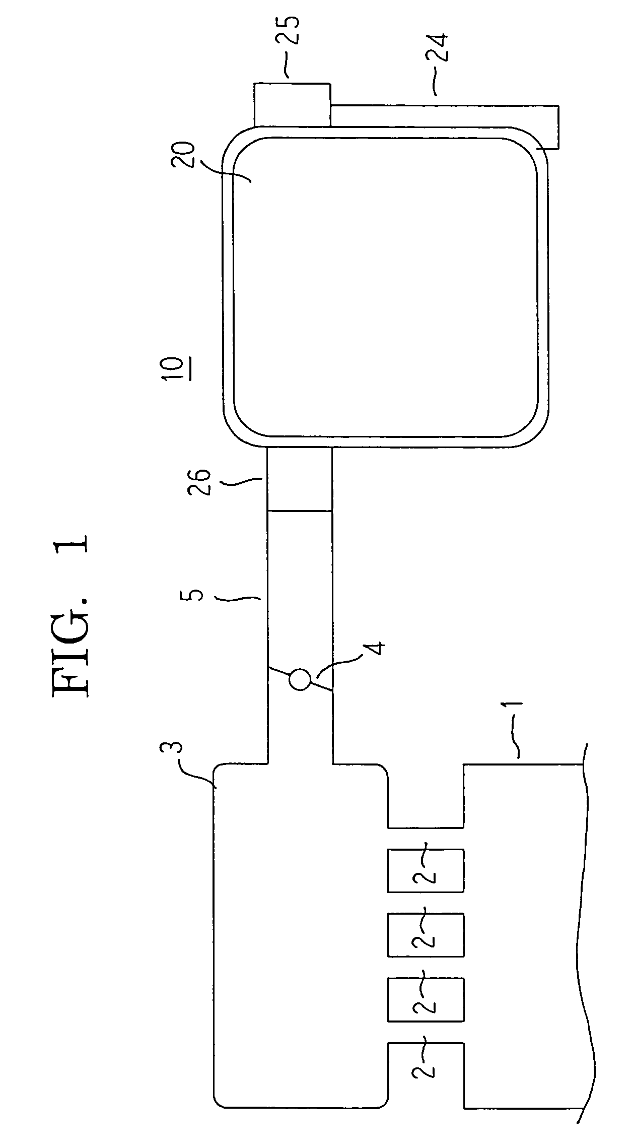
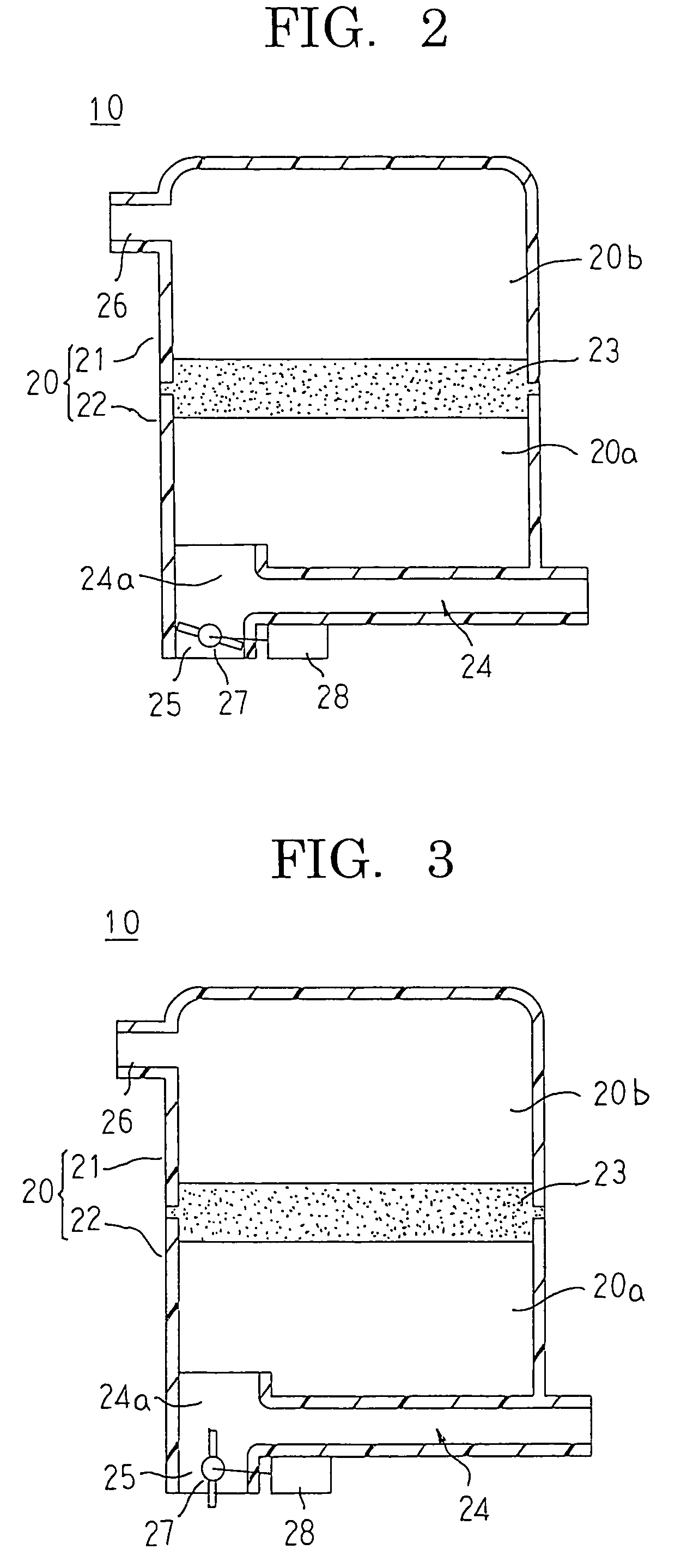
[0032]FIG. 1 is a system configuration diagram employing an engine air intake apparatus according to Embodiment 1 of the present invention, FIG. 2 is a cross section showing a state during low-speed operation in the engine air intake apparatus according to Embodiment 1 of the present invention, and FIG. 3 is a cross section showing a state during high-speed operation in the engine air intake apparatus according to Embodiment 1 of the present invention.

[0033]In FIG. 1, an air intake pipe 5 is connected to a downstream passage 26 of an air intake apparatus 10, and a throttle valve 4 is disposed inside the air intake pipe 5. The air intake pipe 5 is linked to a surge tank 3 at a downstream end. In addition, the surge tank 3 is linked to respective cylinders of an engine 1 by means of an intake manifold 2.

[0034]Next, a specific configuration of the air intake apparatus 10 will be explained with reference to FIGS. 2 and 3.

[0035]The air intake apparatus 10 includes: an air cleaner chamber...

embodiment 2

[0043]FIG. 4 is a cross section showing a state during low-speed operation in an engine air intake apparatus according to Embodiment 2 of the present invention, and FIG. 5 is a cross section showing a state during high-speed operation in the engine air intake apparatus according to Embodiment 2 of the present invention.

[0044]In FIGS. 4 and 5, a passage switching valve 29 is disposed in the low-speed operation air intake passage 24. A valve actuator 30 drives the passage switching valve 29 in accordance with control signals from an engine control apparatus (ECU) (not shown) such that an aperture area of the low-speed operation air intake passage 24 is made variable. A passage cross-sectional area and a passage length of the high-speed operation air intake passage 25 are set to appropriate values with consideration for pulsation effects in the intake air in a similar manner to the low-speed operation air intake passage 24 such that engine intake air flow increases in a prescribed high...

embodiment 3

[0052]FIG. 6 is a cross section showing a state during low-speed operation in an engine air intake apparatus according to Embodiment 3 of the present invention, and FIG. 7 is a cross section showing a state during high-speed operation in the engine air intake apparatus according to Embodiment 3 of the present invention.

[0053]In FIGS. 6 and 7, a passage switching valve 31 is a flap valve, and is disposed so as to adopt a state blocking a high-speed operation air intake passage 25 and a state blocking a low-speed operation air intake passage 24. A valve actuator 28 drives the passage switching valve 31 in accordance with control signals from an engine control apparatus (ECU) (not shown) so as to adopt the state blocking the high-speed operation air intake passage 25 and the state blocking the low-speed operation air intake passage 24.

[0054]Moreover, the rest of this embodiment is configured in a similar manner to Embodiment 2 above.

[0055]In an air intake apparatus 10B configured in th...


PUM

PropertyMeasurementUnit
aperture areaaaaaaaaaaa
rotational frequencyaaaaaaaaaa
rotational frequenciesaaaaaaaaaa

Abstract

An air cleaner chamber is configured such that a filtering member is held between an air cleaner cover and an air cleaner case. A low-speed operation air intake passage and a high-speed operation air intake passage share an outlet passage portion near a dusty space, and are molded integrally on the air cleaner case using a synthetic resin. A passage switching valve is disposed so as to switch an aperture area of the high-speed operation air intake passage. In addition, a valve actuator for driving the passage switching valve is mounted to the air cleaner case.

Description

BACKGROUND OF THE INVENTION[0001]1. Field of the Invention[0002]The present invention relates to an engine air intake apparatus and particularly to an air intake apparatus in which an air intake passage is configured integrally on an air cleaner.[0003]2. Description of the Related Art[0004]In passenger car engines, air intake noise emitted from air intake passage inlet portions accounts for a large share of overall noise during slow running when noise resulting from mechanical operation and vibration of the engine itself, exhaust noise, etc., are comparatively small. Thus, one important task has been to reduce the air intake noise during slow running while ensuring sufficient intake air flow required during high-speed operation to avoid reductions in engine power.[0005]In view of these conditions, in some conventional engine air intake apparatuses, air suction portions are constituted by: a normally-open suction port having an aperture area that is constant; and a variable suction p...

Claims


Application Information

Patent Timeline
Patent Type & Authority Patents(United States)
IPC IPC(8): F02M35/10
CPCF02M35/024Y10S55/21
Inventor SUZUKI, MIKIHIKO
Owner MITSUBISHI ELECTRIC CORP
Why Eureka
Try Eureka