Hammer drill with wobble mechanism and hollow drive shaft

a technology of a wobble mechanism and a hammer drill, which is applied in the field of hand power tools, can solve the problems of power tools, complicated construction, and large number of components, and limit the functions of power tools to two functions

Inactive Publication Date: 2007-10-30
ROBERT BOSCH GMBH
View PDF18 Cites 28 Cited by
  • Summary
  • Abstract
  • Description
  • Claims
  • Application Information

AI Technical Summary

Benefits of technology

[0005]It is therefore an object of the present invention to provide a hand power tool which eliminates the disadvantages of the prior art.
[0007]The hand power tool according to the invention has the following advantages over the prior art: In itself, the hand power tool combines a merely one-stage gear mechanism, with the consequence of a space-saving, compact, lightweight construction, as well as its design as a combination tool, which makes all functions possible, that is, at least drilling, hammer drilling and chiseling.
[0008]A reduction in the number of gear and bearing stages and thus in the number of necessary components is achieved. Bundling the functions together leads to a design that is shorter by about 30 mm, for instance, with at the same time an insignificant increase in the dimensions in height. The reduction in gear and bearing stages increases the efficiency. An overall economy of material and expense is achieved.

Problems solved by technology

A disadvantage of such hand power tools, however, is that in terms of their functions they are limited to two functions, namely hammer drilling and chiseling.
However, these hand power tools have the disadvantage of a complicated, expensive construction with a large number of components, because of the individual gear and bearing stages, and therefore have the disadvantage of reduced efficiency.
Moreover, these hand power tools have a relatively high weight, and because of the internal space required also have correspondingly large dimensions and are therefore not as handy as is desired.

Method used


Image

  • Hammer drill with wobble mechanism and hollow drive shaft
  • Hammer drill with wobble mechanism and hollow drive shaft
  • Hammer drill with wobble mechanism and hollow drive shaft

Examples


Embodiment Construction

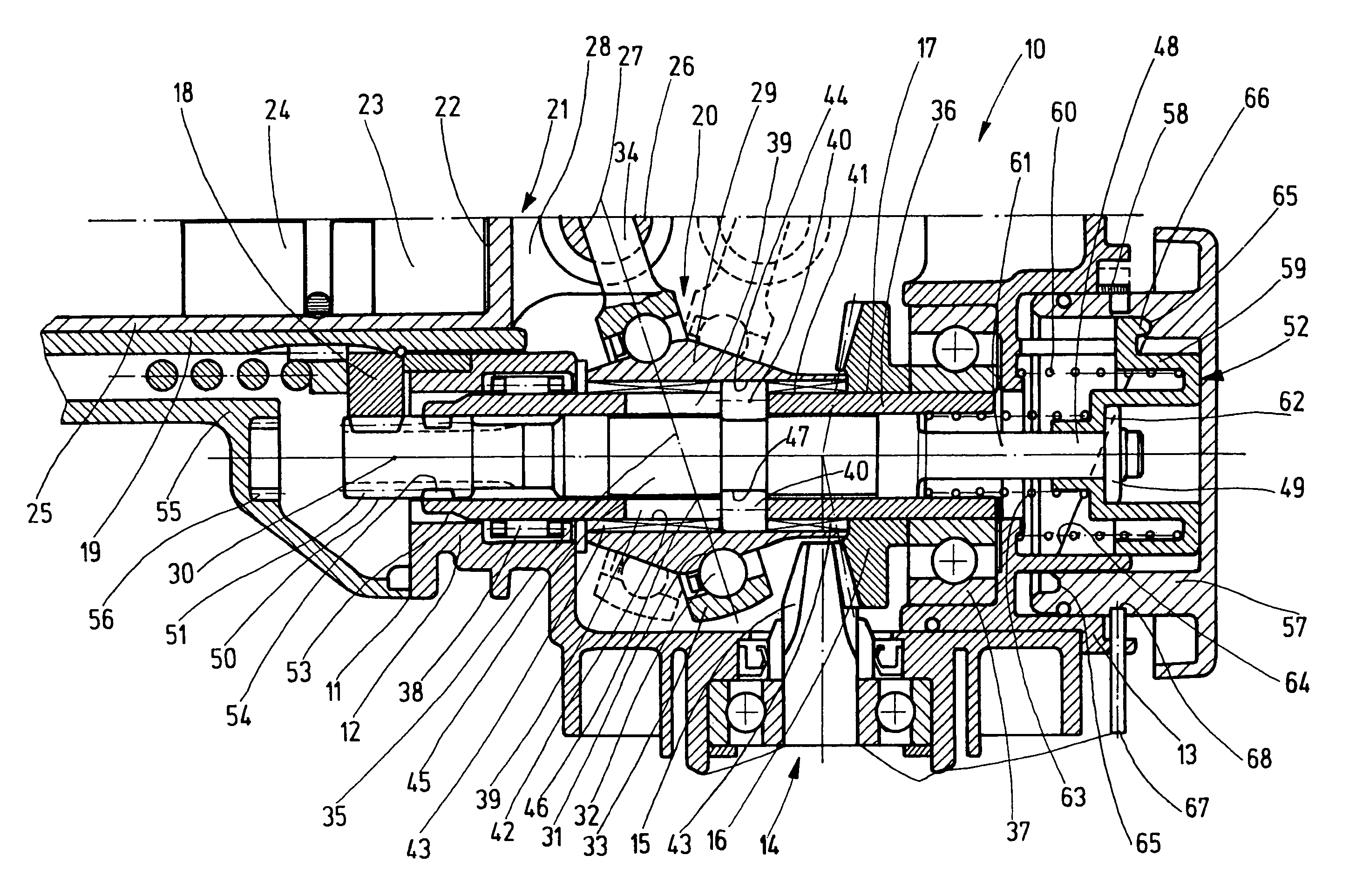
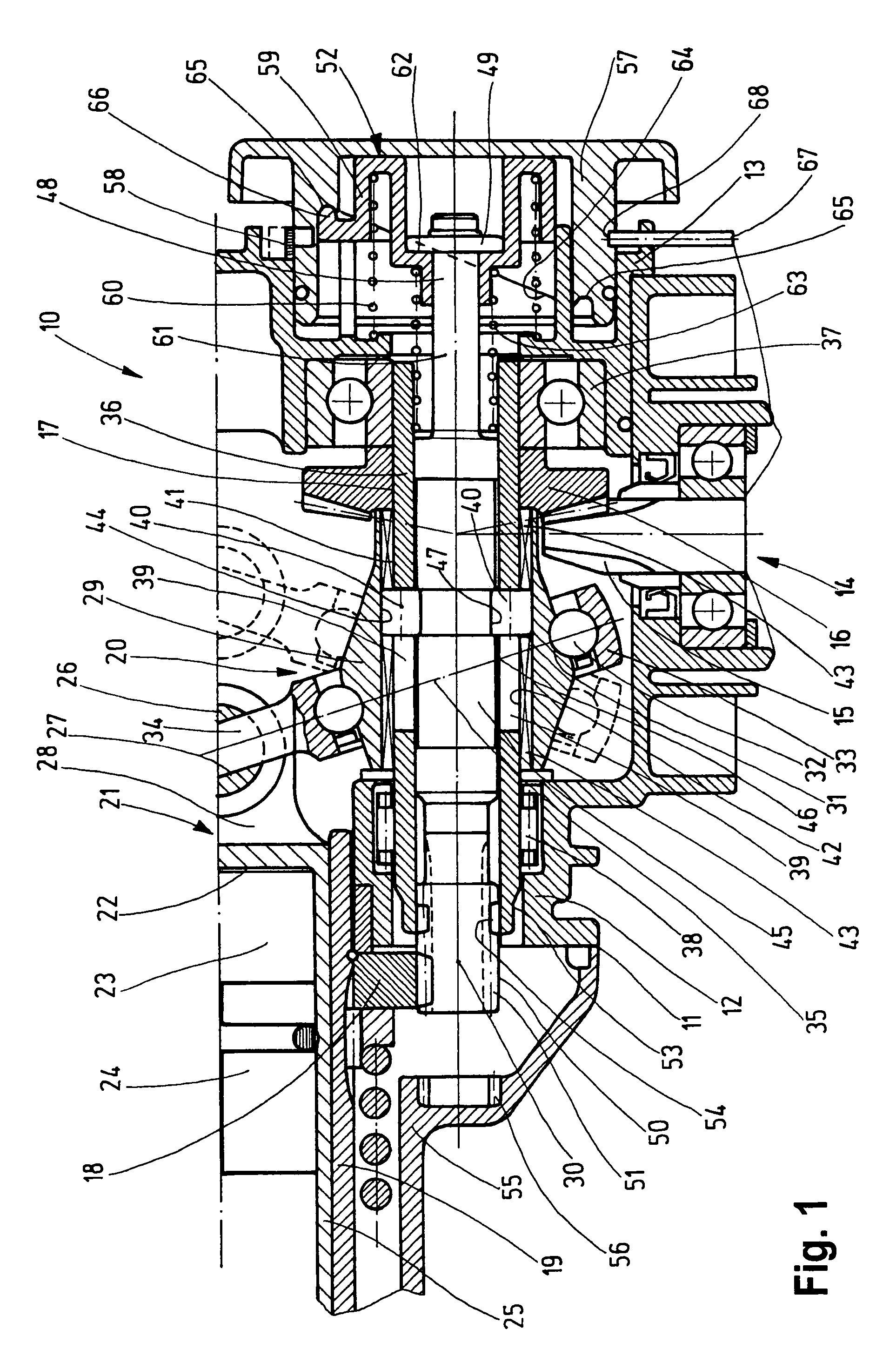
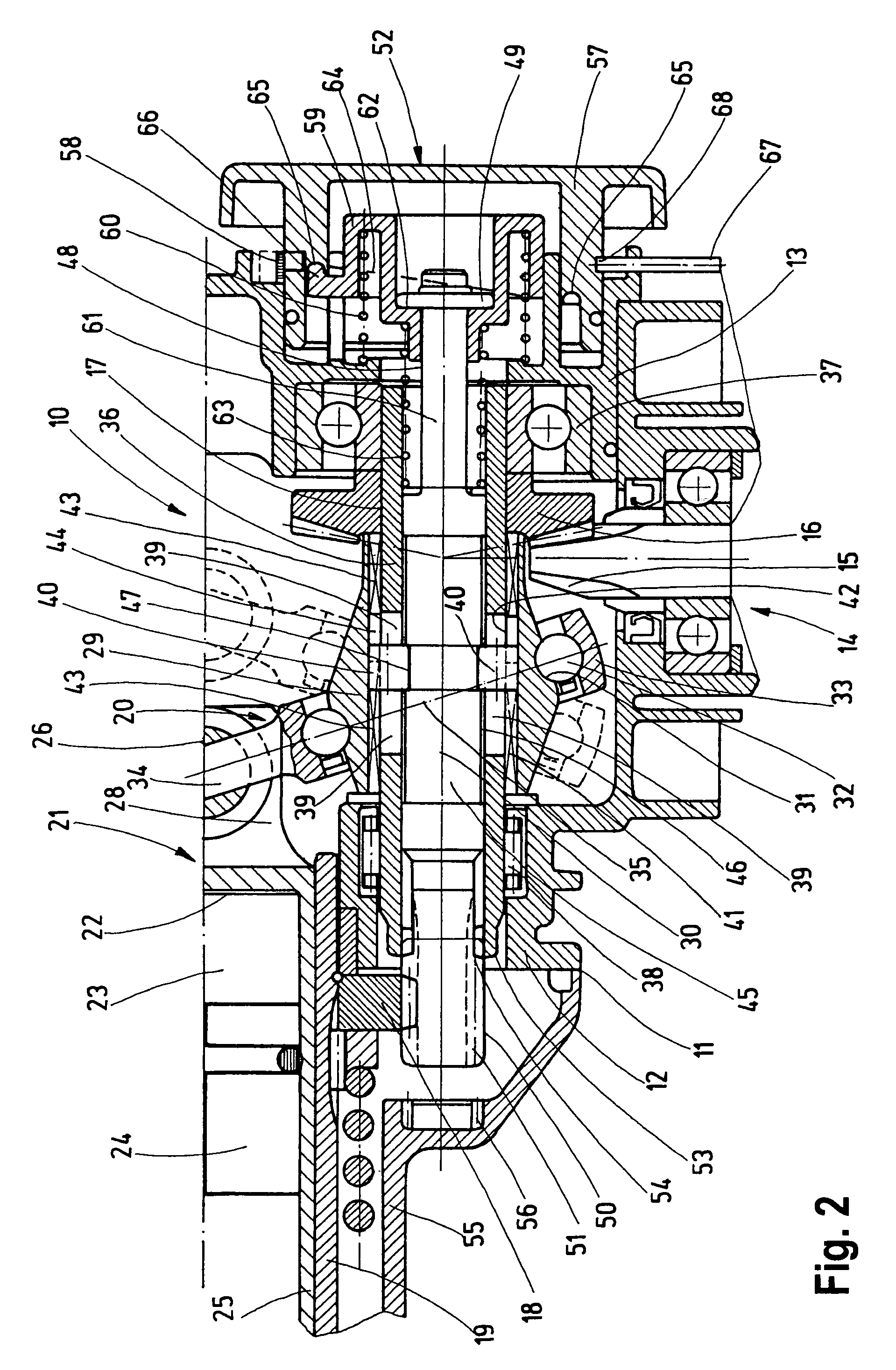
[0014]In the drawings, a detail of interest here is schematically shown of a hand power tool 10 which is embodied in particular as a drilling hammer and / or jackhammer. The hand power tool 10 has a housing 11, which includes a gearbox 12, a bearing flange 13, and a hammering mechanism housing 55. The housing 11 includes an approximately vertically oriented, in particular electrical, drive motor that is not otherwise visible and that via a gear mechanism 14 acts on a downstream drilling and / or hammering mechanism. The gear mechanism 14 has a motor pinion 15, embodied in particular as a conical pinion with an approximately vertical axial course in terms of the drawing.

[0015]The motor pinion 15 is driven by the drive motor, not shown, and meshes with a driving gear wheel 16, which is embodied in particular as a cone wheel. The driving gear wheel 16 is retained axially nondisplaceably and in a manner fixed against relative rotation on a shaft 17. Via the shaft 17 and a gear wheel 18, in ...


PUM

PropertyMeasurementUnit
heightaaaaaaaaaa
axial displacementaaaaaaaaaa
displacementaaaaaaaaaa

Abstract

A hand power tool has a housing, a drive motor and a gear mechanism arranged in the housing. A tool receptacle accommodates a tool, and a gear wheel drives a rotary sleeve in rotation from the drive motor and the gear mechanism and thereby the tool receptacle. A hammering mechanism is located inside the rotary sleeve and drivable translationally via a wobble gear. The gear mechanism has a driving gear wheel meshing with a motor pinion and arranged on a shaft by which the wobble gear mechanism is drivable to revolve. The shaft is configured as a hollow shaft on which the driving gear wheel is retained nondisplaceably and in a manner fixed against rotation. The wobble gear mechanism is located adjacent to the driving gear wheel on the shaft rotatably and couplably to the hollow shaft.

Description

CROSS-REFERENCE[0001]The invention described and claimed hereinbelow is also described in DE 102004026845.2, filed Jun. 2, 2004. This German Patent Application, whose subject matter is incorporated here by reference, provides the basis for a claim of priority of invention under 35 U.S.C. 119 (a)-(d).BACKGROUND OF THE INVENTION[0002]The invention is based on a hand power tool, in particular a drilling hammer and / or jackhammer.[0003]Known hand power tools of this type have an L-shaped construction, in which the gear mechanism is embodied as a single-stage cone wheel gear, and the drive mechanism of the hammering mechanism is embodied as a wobble gear mechanism. Both the driving gear wheel embodied as a cone wheel and the wobble gear mechanism are located on one shaft, which makes for a space-saving, compact mode of construction. A disadvantage of such hand power tools, however, is that in terms of their functions they are limited to two functions, namely hammer drilling and chiseling....

Claims


Application Information

Patent Timeline
Patent Type & Authority Patents(United States)
IPC IPC(8): B25D16/00B23B45/16B25D11/06B25D11/10B25F5/00
CPCB25D11/062B25D16/006B25D2216/0015B25D2250/245B25D2216/0038B25D2216/0076B25D2216/0023
Inventor BRAUN, WILLY
Owner ROBERT BOSCH GMBH
Why Eureka
Try Eureka