Torque converter slip control for multi-displacement engine

a technology of torque converter and multi-displacement engine, which is applied in the direction of gearing control, gearing elements, gearing rings, etc., can solve the problem of reducing the system's transparency to vehicle passengers

Active Publication Date: 2007-10-30
FCA US
View PDF10 Cites 30 Cited by
  • Summary
  • Abstract
  • Description
  • Claims
  • Application Information

AI Technical Summary

Problems solved by technology

Unfortunately, in some instances, such slip rate reductions after transitioning to a partial-displacement mode undesirably increase vehicle noise, vibration, and harshness (NVH) levels, particularly at lower engine and vehicle speeds, thereby reducing the system's transparency to vehicle passengers.

Method used


Image

  • Torque converter slip control for multi-displacement engine
  • Torque converter slip control for multi-displacement engine
  • Torque converter slip control for multi-displacement engine

Examples


Embodiment Construction

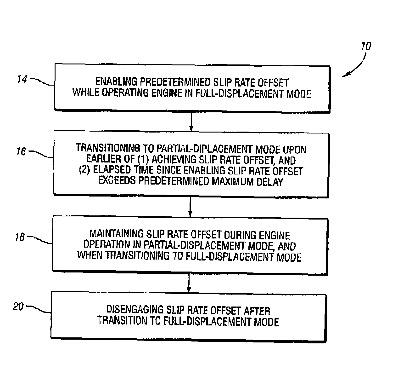
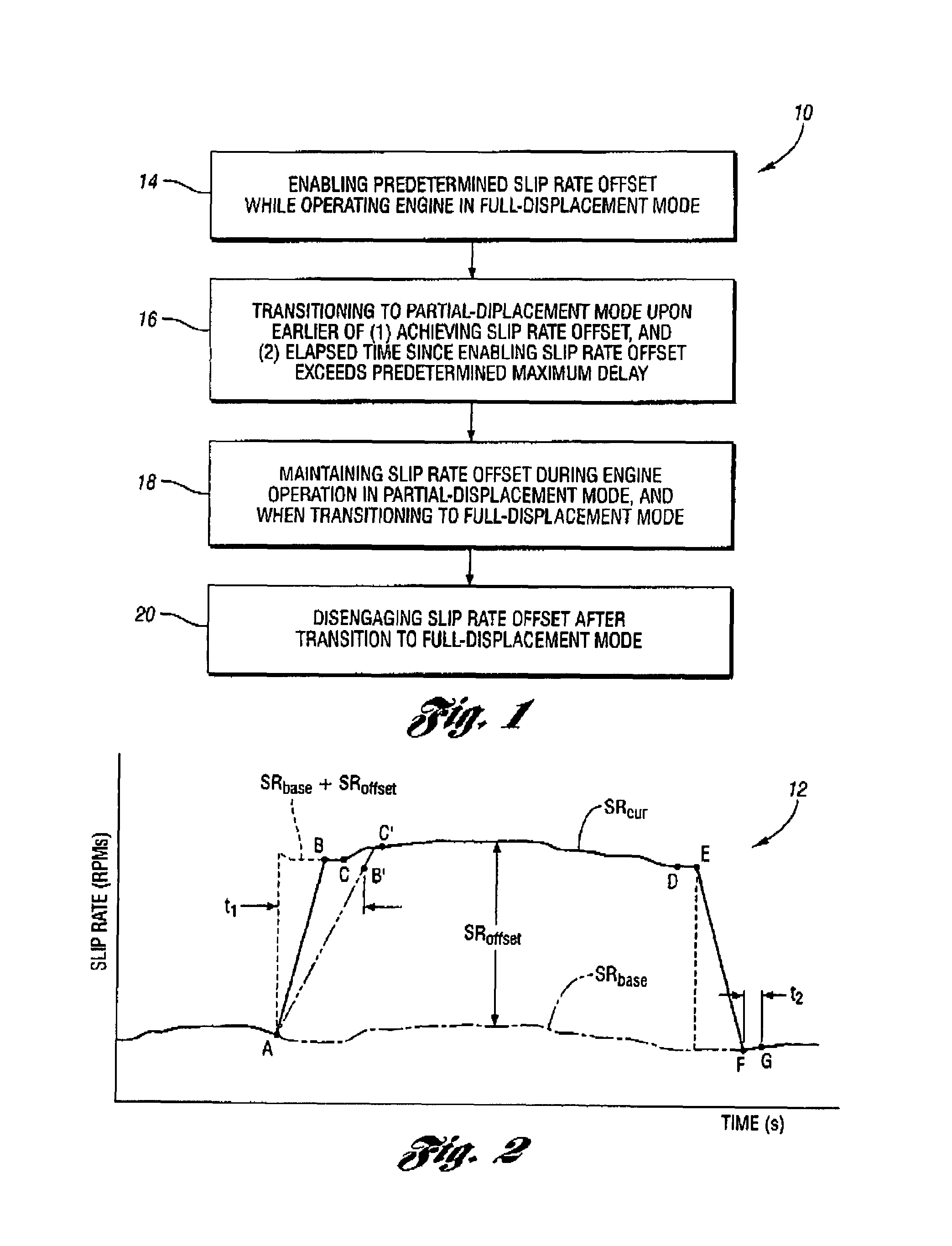
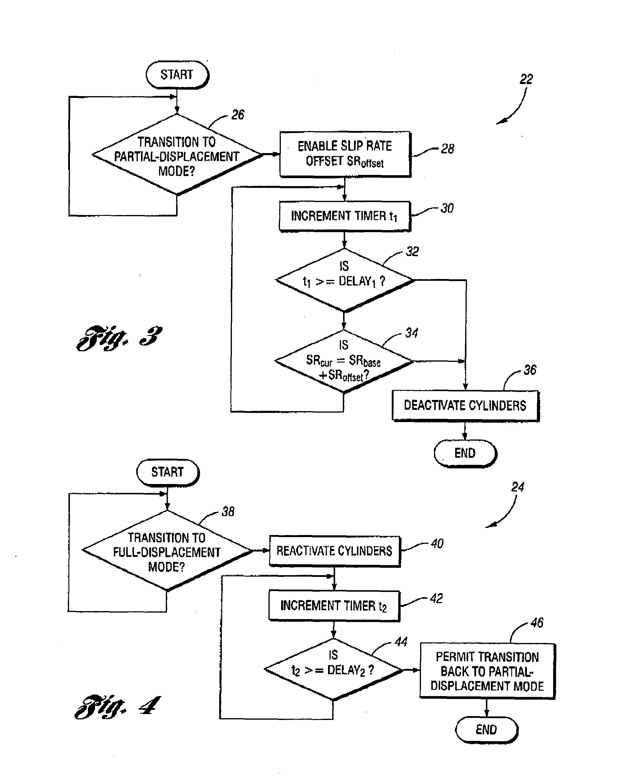
[0014]A method 10 for controlling slip in a torque converter coupled to a multi-displacement engine is generally illustrated in FIG. 1, while an exemplary plot 12 of torque converter slip rate versus time, illustrating a current torque converter slip rate SRcur as the engine transitions from a full-displacement mode to a partial-displacement mode, and again back to a full-displacement mode, is shown in FIG. 2. While the invention contemplates any suitable hydraulic and / or electromechanical system for deactivating the given cylinder, including deactivatable valve train components, a constructed embodiment features an eight-cylinder engine in which four cylinders are selectively deactivated through use of deactivatable valve lifters as disclosed in U.S. patent publication no. US 2004 / 0244751 A1, the teachings of which are hereby incorporated by reference.

[0015]As seen in FIGS. 1 and 2, the method 10 generally includes enabling, at block 14, a predetermined torque converter slip rate o...


PUM


Abstract

Prior to transitioning a multiple-displacement engine from a full-displacement engine operating mode to a partial-displacement engine operating mode, a base slip rate of a torque converter coupled to the engine engine is increased by a predetermined slip rate offset. The engine is then transitioned to partial-displacement mode upon the earlier of either achieving the desired offset slip rate, or once a maximum time delay has occurred since the slip rate offset was enabled. An offset slip rate is maintained throughout partial-displacement engine operation, and through a transition back to a full-displacement mode. The slip rate offset is removed or disenabled once the engine is again operating in the full-displacement mode. The slip rate offset is either a calibratable constant or is determined as a function of one or more suitable engine or vehicle operating parameters affecting vehicle NVH levels, such as engine speed and vehicle speed.

Description

FIELD OF THE INVENTION[0001]The invention relates generally to multi-displacement internal combustion engines and, more particularly, to methods and computer-executable code for controlling slip in a torque converter coupled to a multi-displacement engine to smooth transitions between full- and partial-displacement engine operating modes.BACKGROUND OF THE INVENTION[0002]The prior art teaches equipping vehicles with “variable displacement,”“displacement on demand,” or “multiple displacement” internal combustion engines in which one or more cylinders may be selectively “deactivated,” for example, to improve vehicle fuel economy when operating under relatively low-load conditions. Typically, the cylinders are deactivated through use of deactivatable valve train components, such as the deactivating valve lifters as disclosed in U.S. patent publication no. US 2004 / 0244751 A1, whereby the intake and exhaust valves of each deactivated cylinder remain in their closed positions notwithstandi...

Claims


Application Information

Patent Timeline
Patent Type & Authority Patents(United States)
IPC IPC(8): F16H61/48
CPCF16H61/48B60W30/20F16H57/0006F16H59/74F16H2059/467Y10T477/636Y10T477/6353Y10T477/631Y10T477/633Y10T477/6333Y10T477/6357Y10T477/6745
Inventor BOONE, MICHAEL ADUTY, MARK JMITCHELL, JOHN SPANNONE, GREGORY MPRUCKA, MICHAEL JSULLIVAN, MARC H
Owner FCA US
Why Eureka
Try Eureka