Reciprocating motor

a reciprocating motor and motor technology, applied in the direction of magnetic circuit rotating parts, piston pumps, magnetic circuit shapes/forms/construction, etc., can solve the problems of increasing the number of parts, complicated assembly process of magnets, lowering product productivity, etc., to simplify the manufacturing process of magnets, reduce cost, and improve product productivity

Active Publication Date: 2007-10-30
LG ELECTRONICS INC
View PDF4 Cites 27 Cited by
  • Summary
  • Abstract
  • Description
  • Claims
  • Application Information

AI Technical Summary

Benefits of technology

[0013]Therefore, an object of the present invention is to provide a reciprocating motor capable of improving productivity of a product and reducing the cost by integrally manufacturing a magnet in a cylindrical shape and simplifying the manufacturing process of the magnet and the assembly process of the magnet.

Problems solved by technology

However, in the conventional reciprocating motor, because a plurality of the magnets 22 should be separately installed at the magnet frame 21 after they are individually fabricated, the assembly process of the magnets 22 is complicated, thereby lowering productivity of products.
Therefore, the number of parts is increased because of the use of the retainer ring 23 to thereby increase a manufacturing cost and complicate the assembly process.

Method used


Image

  • Reciprocating motor
  • Reciprocating motor
  • Reciprocating motor

Examples


Embodiment Construction

[0026]Hereinafter, reference will now be made in detail to the preferred embodiments of the present invention, examples of which are illustrated in the accompanying drawings.

[0027]As shown in FIGS. 4 and 5, a reciprocating motor in accordance with the present invention includes an outer stator 111 having a cylindrical shape by radially stacking a plurality of lamination sheets 114 on an outer side of a winding coil 115, an inner stator 112 disposed in an inner circumference of the outer stator 111 at a certain air gap from an inner circumferential surface of the outer stator 111 and having a cylindrical shape by radially stacking a plurality of lamination sheets 113, and a movable unit 120 disposed between the outer stator 111 and the inner stator 112 and linearly reciprocating.

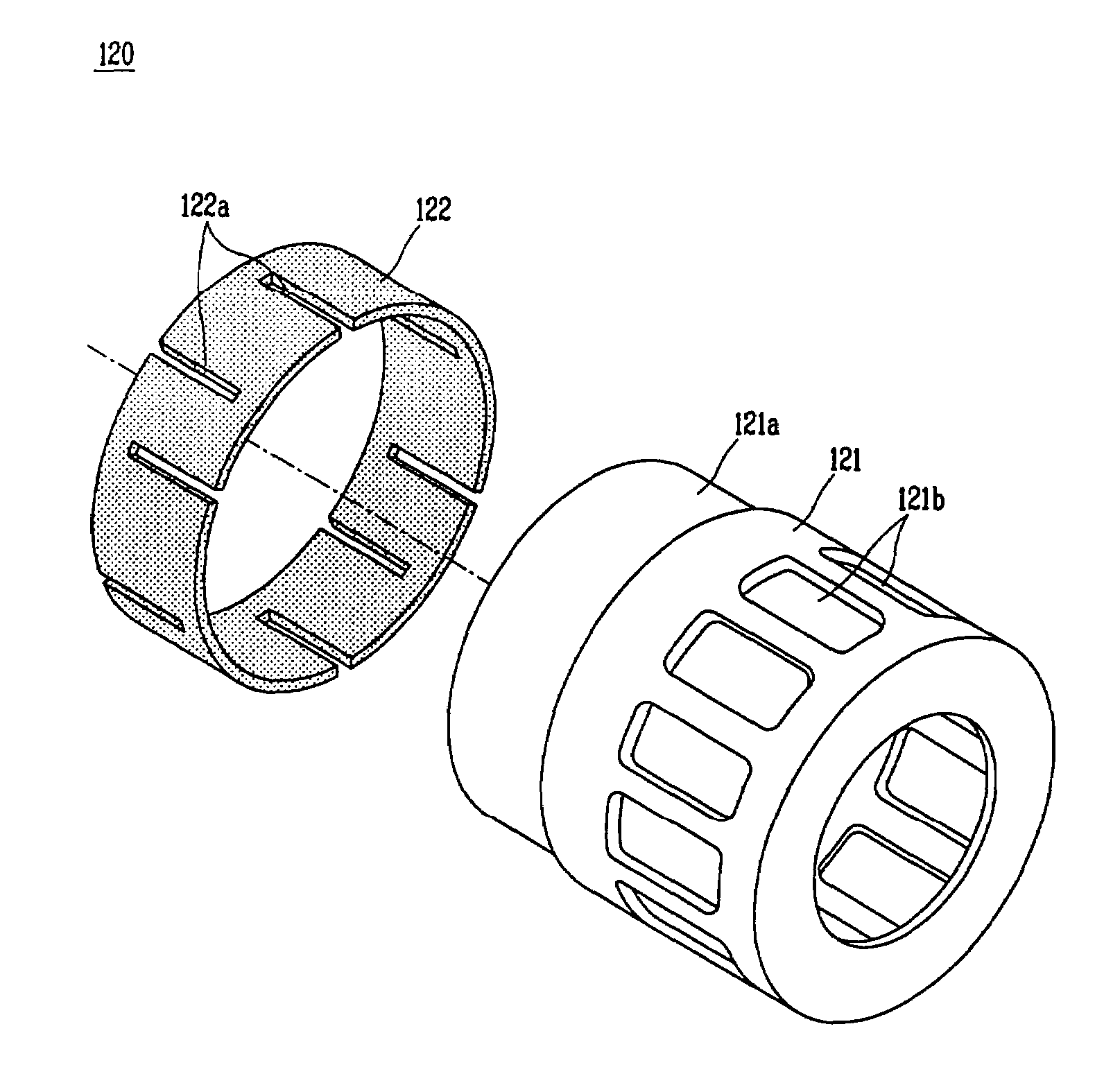
[0028]As shown in FIG. 6, the movable unit 120 includes a magnet frame 121 disposed between the outer stator 111 and the inner stator 112, and a cylindrical magnet 122 formed as a single body and installed on...


PUM


Abstract

A reciprocating motor includes a pair of stators and a cylindrical magnet formed as a single body and disposed between the stators, for linearly reciprocating. Accordingly, it allows facilitating a job of manufacturing and installing the magnet, so that productivity can be improved.

Description

BACKGROUND OF THE INVENTION[0001]1. Field of the Invention[0002]The present invention relates to a reciprocating motor, and more particularly, to a reciprocating motor which enables to improve productivity and assembling of a magnet.[0003]2. Description of the Background Art[0004]In general, a reciprocating motor has a magnetic flux in a plane form, and a movable unit disposed between an outer stator and an inner stator linearly reciprocates according to variation of the magnetic flux.[0005]As shown in FIGS. 1 and 2, the conventional reciprocating motor includes an outer stator 11 having a cylindrical shape by radially stacking a plurality of lamination sheets 14 to an outer side of a winding coil 15, an inner stator 12 disposed in an inner circumference of the outer stator 11 at a certain air gap from an inner circumferential surface of the outer stator 11 and having a cylindrical shape by radially stacking a plurality of lamination sheets 13, and a movable unit 20 disposed between...

Claims


Application Information

Patent Timeline
Patent Type & Authority Patents(United States)
IPC IPC(8): H02K33/00H02K1/34F01B31/14F02B63/04F25B9/00H02K1/27H02K33/16H02K33/18H02K35/00H02K35/02H02K41/02
CPCH02K33/16H02K35/02H02K41/02
Inventor SONG, GYE-YOUNGLEE, JONG-KOO
Owner LG ELECTRONICS INC
Why Eureka
Try Eureka