Electrical vehicle controller
a technology of electric vehicle controller and controller, which is applied in the direction of dynamo-electric converter control, multiple dynamo-motor starters, electric devices, etc., can solve the problems of slipping of wheels and idle running of wheels, and achieve simple and rapid/accurate torque correction control, the effect of reducing the torque pattern
- Summary
- Abstract
- Description
- Claims
- Application Information
AI Technical Summary
Benefits of technology
Problems solved by technology
Method used
Image
Examples
first embodiment
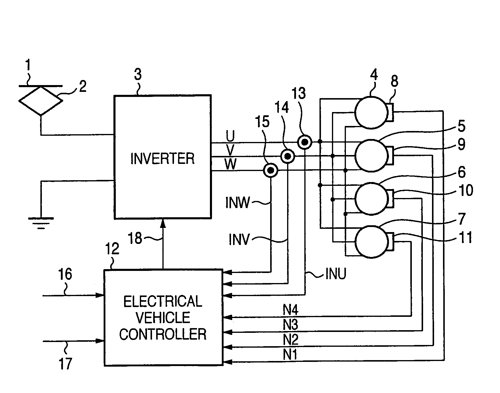
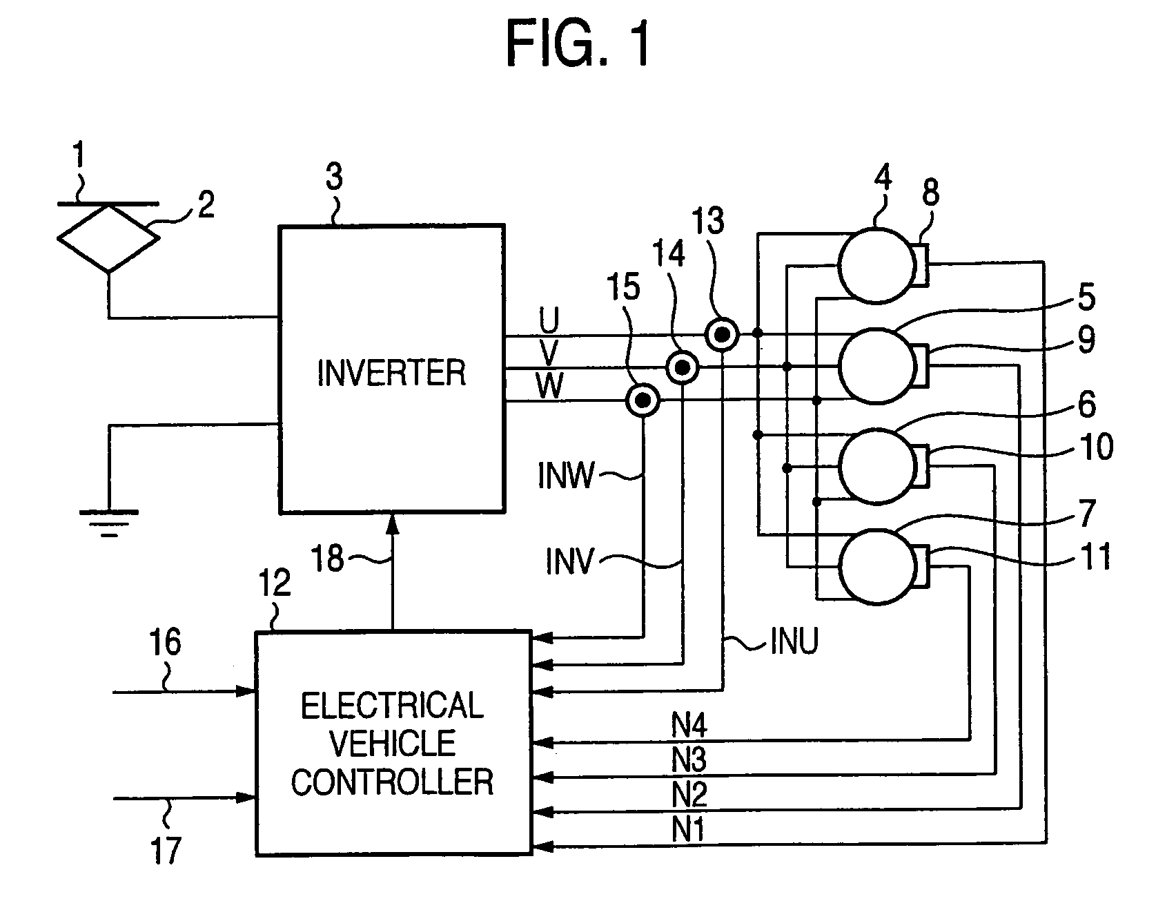
[0008]FIG. 1 is a construction diagram showing the relationship of an electrical vehicle controller, an inverter and AC electric motors according to a first embodiment. In FIG. 1, DC power collected from an overhead wire 1 through power collector 2 is supplied to an inverter 3 and converted to three-phase AC power of U-phase, V-phase and W-phase. AC electric motors 4 to 7 for an electrical vehicle such as induction motors or the like are driven by the three-phase AC power as the output of the inverter 3. The rotational numbers N1 to N4 of the respective AC electric motors 4 to 7 which are detected by pulse generators 8 to 11 are input to an electrical vehicle controller 12. Furthermore, input current INU, INV, INW of the AC electric motors 4 to 7 which are detected by current detectors 13 to 15 are input to the electrical vehicle controller 12. Furthermore, a driver's platform instruction signal 16 of a power running notch instruction from a driver's platform (not shown) and a load ...
second embodiment
[0014]FIG. 4 is a block diagram showing an electrical vehicle controller 12 according to a second embodiment of the invention. In FIG. 4, 16 to 22, 28 to 30 represent the same elements as the first embodiment.
[0015]In FIGS. 1 and 4, the first frequency deviation ΔFM1 is calculated in the first subtracter 22 as in the case of the first embodiment. When the first frequency deviation ΔFM1 is input to first time-differentiating means 31, a first time variation amount ΔFM1D is calculated by time-differentiating the first frequency deviation ΔFM1 from a predetermined time measurement start time for a predetermined time t1. Furthermore, the first frequency deviation ΔFM1 is input to second time-differentiating means 32, and time-differentiated from a predetermined time measurement start time for a predetermined time t2 longer than the time t1 to calculate a temporary time variation amount ΔFM2D(t2).
[0016]Subsequently, in converting means 33, the temporary time variation amount ΔFM2D(t2) is...
third embodiment
[0019]FIG. 6 is a block diagram showing an electrical vehicle controller 12 according to a third embodiment. In FIGS. 1 and 6, 16 to 24, 28 to 30 represent the same elements as the first embodiment.
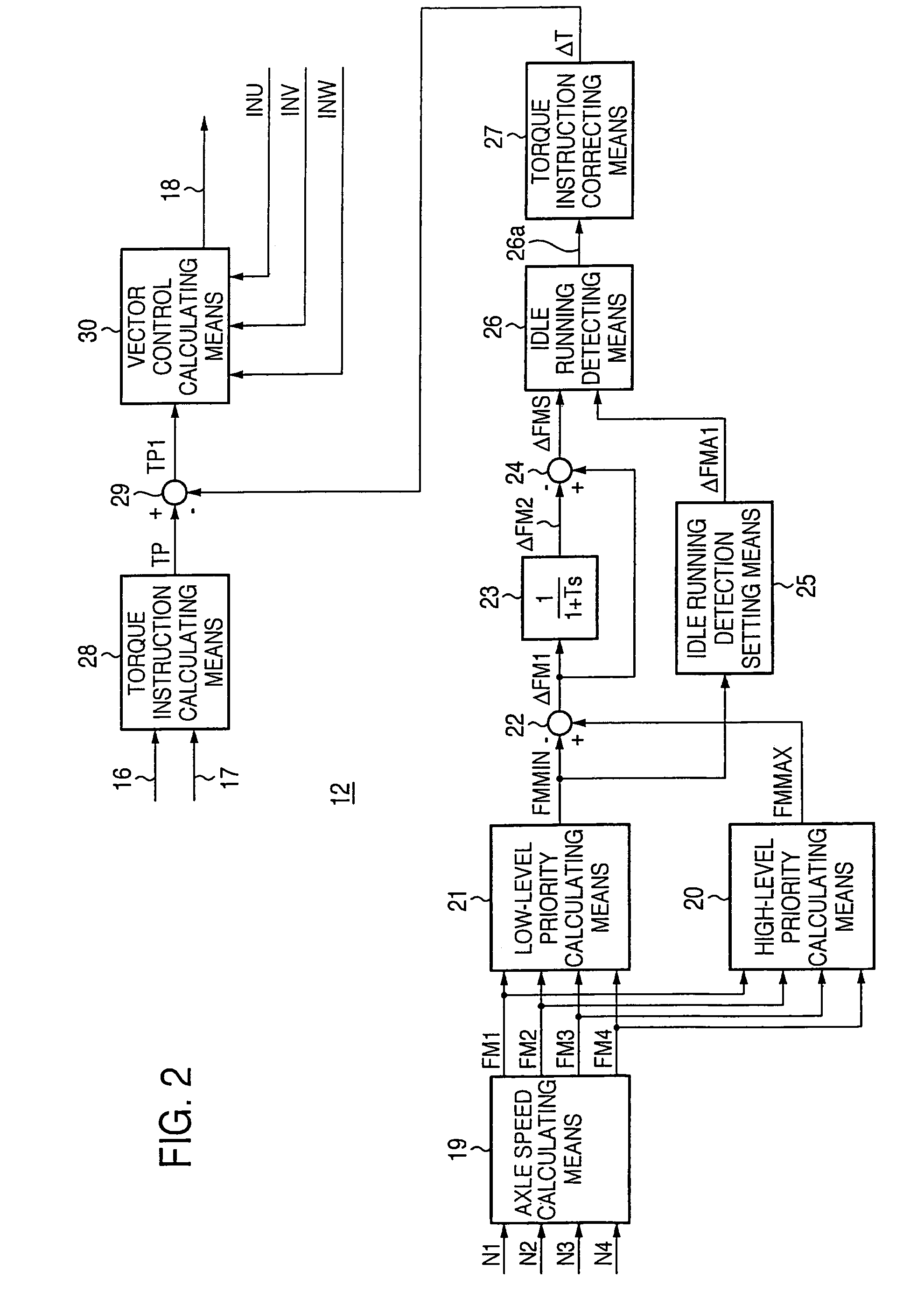
[0020]In FIGS. 1 and 6, the first frequency deviation ΔFM1 is calculated in the first subtracter 22 as in the case of the first embodiment. Furthermore, the first frequency deviation ΔFM1 is input to the primary delay means 23, and the second frequency deviation ΔFM2 is calculated as the primary delay system. Subsequently, in the second subtracter 24, the second frequency deviation ΔFM2 is subtracted from the first frequency deviation ΔFM1 to calculate the idle running frequency deviation ΔFMS. Then, the idle running detection set value ΔFMA2 for judging the idle running at the frequency level is output from the idle running detection setting means 38. In this embodiment, the idle running detection set value ΔFMA2 is set by a predetermined value, for example so that the acceleration is sw...
PUM
 Abstract
Description
Claims
Application Information
 - R&D
- Intellectual Property
- Life Sciences
- Materials
- Tech Scout
- Unparalleled Data Quality
- Higher Quality Content
- 60% Fewer Hallucinations
Browse by: Latest US Patents, China's latest patents, Technical Efficacy Thesaurus, Application Domain, Technology Topic, Popular Technical Reports.
© 2025 PatSnap. All rights reserved.Legal|Privacy policy|Modern Slavery Act Transparency Statement|Sitemap|About US| Contact US: help@patsnap.com


