High resolution pulse width modulator

a pulse width modulator, high-resolution technology, applied in pulse manipulation, pulse technique, single output arrangement, etc., can solve the problem of not being able or desirable to include a high-speed clock for pulse width modulation, unable to achieve the desired resolution of traditional digital pulse width modulation techniques, and unable to achieve the desired resolution

Active Publication Date: 2007-10-30
APPLE INC
View PDF9 Cites 102 Cited by
  • Summary
  • Abstract
  • Description
  • Claims
  • Application Information

AI Technical Summary

Problems solved by technology

One issue with pulse width modulation is the resolution of the modulation.
Unfortunately, in many cases it may not be possible or desirable to include a high speed clock for pulse width modulation.
In these cases traditional techniques for digital pulse width modulation may be unable to achieve the desired resolution.
Other solutions that can provide higher resolution suffer from other limitations, such as unacceptable difficulty in adapting these solutions to digital control

Method used


Image

  • High resolution pulse width modulator
  • High resolution pulse width modulator
  • High resolution pulse width modulator

Examples


Embodiment Construction

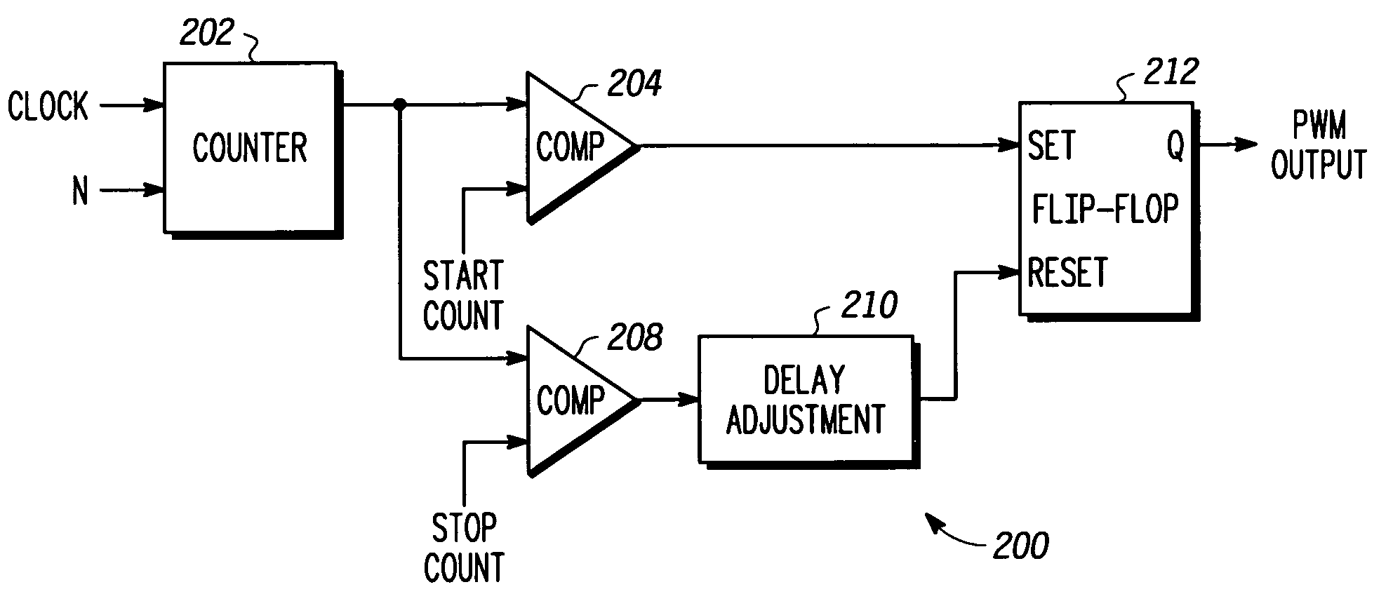
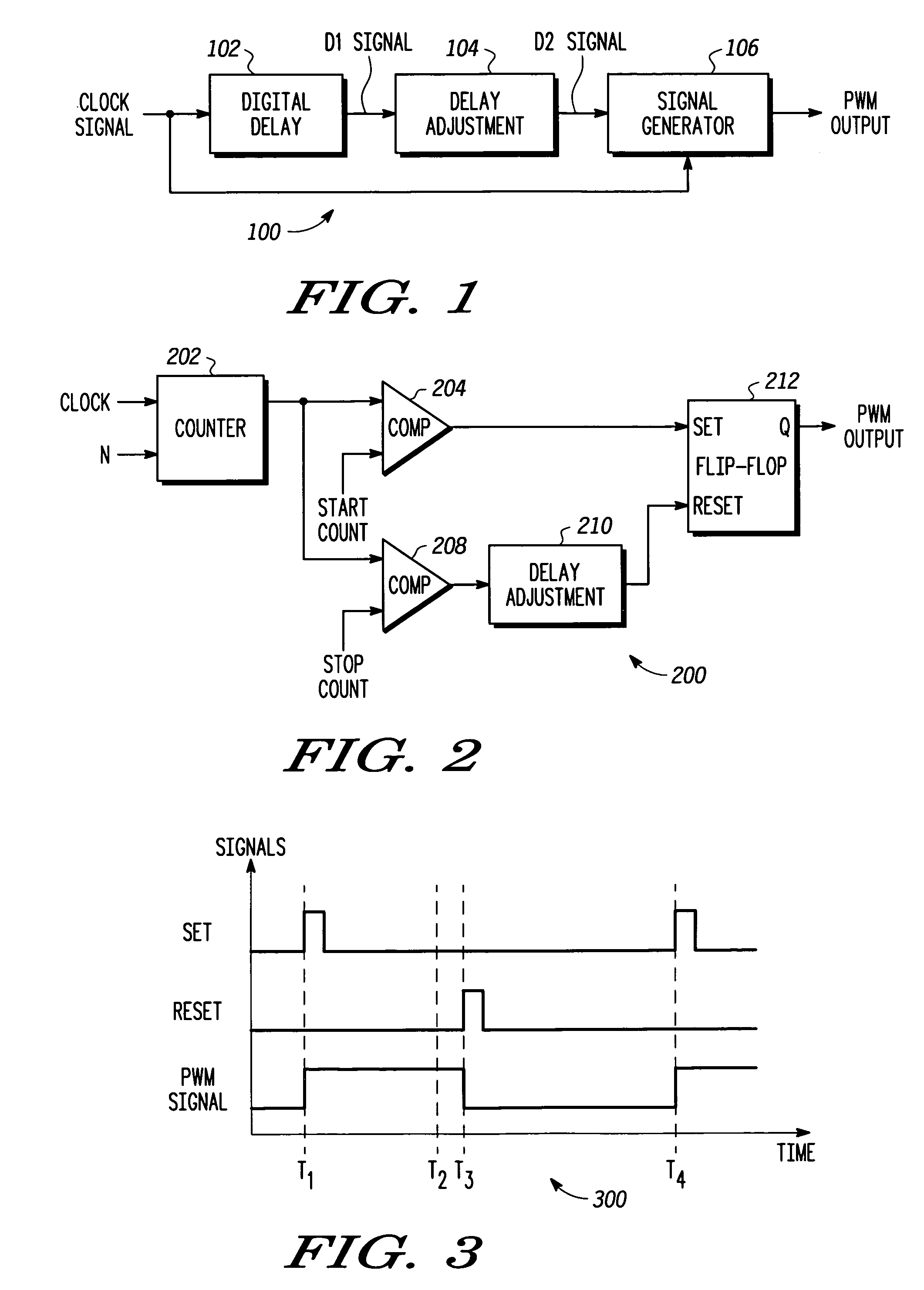
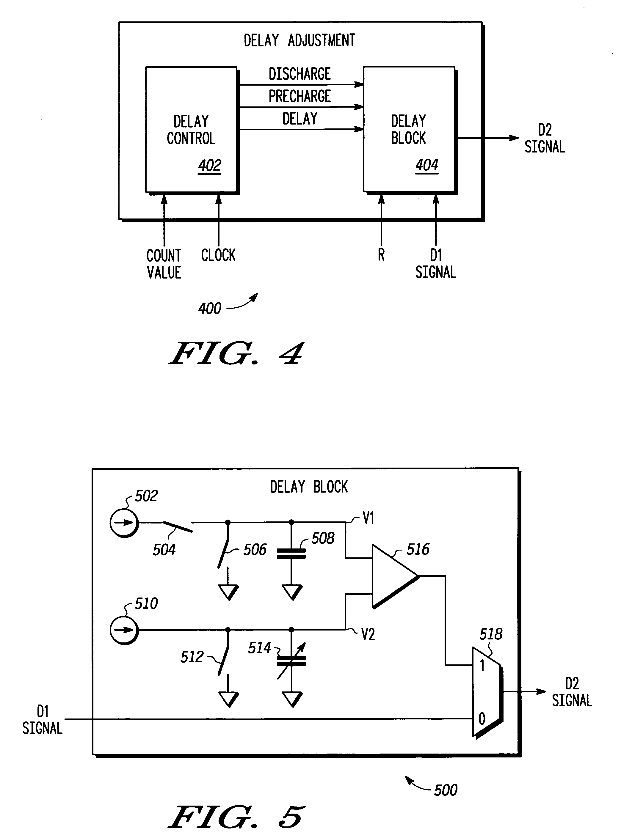
[0016]The present invention provides a pulse width modulator and method that facilitates high resolution pulse width modulation. The pulse width modulator creates a pulse width modulated signal having a duty cycle that is proportional to a controllable delay in the modulator. The pulse width modulator combines a first digitally controllable delay with a delay adjustment to provide the controllable delay that facilitates high resolution pulse width modulation.

[0017]Turning now to FIG. 1, a pulse width modulator 100 is illustrated schematically. The pulse width modulator 100 includes a digital delay 102, a delay adjustment 104 and a signal generator 106. The pulse width modulator 100 receives a clock signal and produces a pulse width modulated output. Specifically, the pulse width modulator 100 produces a signal having a duty cycle that is proportional to the delay in the digital delay 102 and delay adjustment 104. By controlling the delay in the digital delay 102 and delay adjustment...


PUM


Abstract

A pulse width modulator (100) and method that facilitates high resolution pulse width modulation is provided. The pulse width modulator (100) creates a pulse width modulated signal having a duty cycle that is proportional to a controllable delay in the modulator. The pulse width modulator combines a first digitally controllable delay (102) with a delay adjustment (104) to provide the controllable delay. In one embodiment, a digital counter (202) is used to provide coarse delay, with the delay adjustment device (210) coupled to the digital counter (202) to provide the fine, high resolution, delay control. Together the digital counter (202) and delay adjustment device (210) provide high resolution pulse width modulation. In one particular implementation, the analog delay adjustment device (100) comprises a delay block (500) designed to provide delay adjustment that is selectively controllable by changing a capacitance in the device.

Description

FIELD OF THE INVENTION[0001]This invention generally relates to electronic devices, and more specifically relates to pulse width modulators.BACKGROUND OF THE INVENTION[0002]Electronic devices are becoming increasingly important in everyday modern life. Many electronic devices use pulse width modulation for a variety of purposes. In general, pulse width modulation is a technique where a continuous or analog signal is represented by a digital signal in which the duty cycle of the digital signal, over some period of time, varies directly with the value of the original analog signal. Duty cycle is the ratio of two numbers: the time in one period that signal is at logic high (or low) divided by the total period. This is usually represented as a percentage. The resulting digital signal is said to be Pulse Width Modulated. This signal can be converted back into analog form by the simple expedient of passing it through a low analog filter.[0003]Pulse width modulation is used for a variety o...

Claims


Application Information

Patent Timeline
Patent Type & Authority Patents(United States)
IPC IPC(8): H03K5/13
CPCH03K7/08
Inventor STANLEY, MICHAEL E.
Owner APPLE INC
Why Eureka
Try Eureka