Intelligent flame scanner

a scanner and intelligent technology, applied in the field of intelligent flame scanners, can solve the problems of large space required for routing cable bundles to the processing electronics, high initial capital outlay costs, and relatively limited operation life of ultraviolet flame scanners based on geiger mueller tubes, so as to reduce cabling requirements

Inactive Publication Date: 2007-10-30
GENERAL ELECTRIC TECH GMBH
View PDF15 Cites 48 Cited by
  • Summary
  • Abstract
  • Description
  • Claims
  • Application Information

AI Technical Summary

Benefits of technology

[0011]It is an object of the present invention to provide a flame scanner having reduced cabling requirements.
[0012]It is another object of the present invention to provide a flame scanner having reduced cabling requirements while maintaining suitable redundancy and integration to bus.

Problems solved by technology

Because of the size of each double-shielded cable as well as the number of double-shielded cables, one being required for each flame scanner, a considerable amount of space is necessary for routing cable bundles to the processing electronics.
Additionally, because of the type and number of cables required, high initial capital outlay costs are required.
Ultraviolet flame scanners based on Geiger mueller tubes require extensive maintenance and have relatively limited operational lives as well as unsafe failure modes.
Conventional flame scanners do not differentiate between, or even recognize, different colors.
However, this flame scanner cannot, at the same time, recognize the coal flame.
Thus, this flame scanner is somewhat useful for monitoring oil flames, but limited in monitoring coal flames.
Utilizing multiple types of flame scanners results in higher initial capital outlays, as well as increased maintenance costs.

Method used


Image

  • Intelligent flame scanner
  • Intelligent flame scanner
  • Intelligent flame scanner

Examples


Embodiment Construction

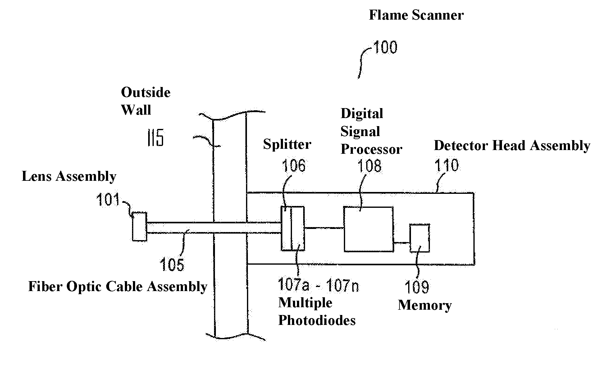
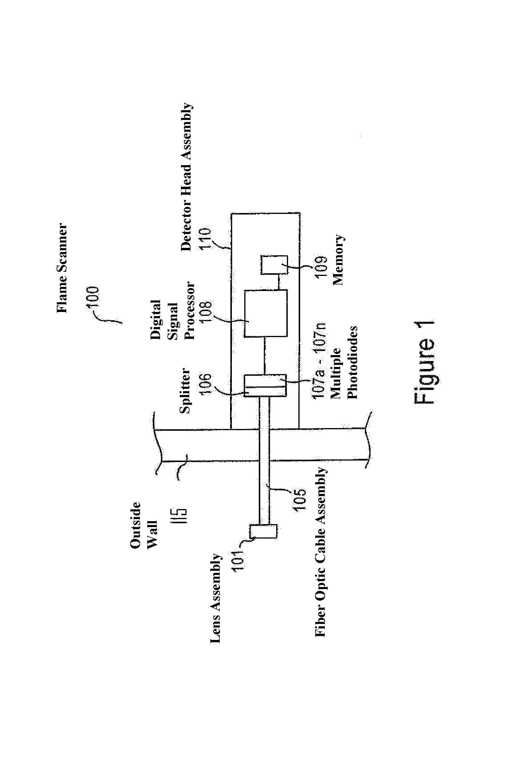
[0031]With reference to the Figures, and particularly FIG. 1, included in a flame scanner 100 of the present invention are a lens assembly 101, a fiber optic cable assembly 105, and a detector head assembly 110. The detector head assembly 110 mounts to an outside wall 115 of a combustion chamber, while the lens assembly 101 is positioned inside the combustion chamber, with the fiber optic cable assembly 105 connecting the detector head assembly 110 and the lens assembly 101 through the outside wall 115. Preferably, all metal components of the lens assembly 101 and the fiber optic cable assembly 105 that are subjected to high heat are constructed of type 304 stainless steel. Flame scanner 100 may be, as desired, utilized in either tangential fired (T-fired) or wall-fired boilers, as well as used with any, or all of, coal-, oil-, gas-, and / or other fuel-fired burners. The detector head assembly 110 preferably is configured such that cooling and / or purge air may be connected, as desire...


PUM


Abstract

Techniques for determining a characteristic of a flame are provided by the present invention. Provided are methods as well as devices. A flame is monitored across a contiguous spectral range to detect light emitted by the monitored flame. The contiguous spectral range is segmented into a plurality of discrete ranges, and detected light across each of the one or more of the plurality of discrete ranges is respectively processed to determine at least one characteristic of the flame.

Description

FIELD OF THE INVENTION[0001]The present invention is related to a flame scanner for monitoring flames produced by a fossil fuel fired combustion chamber, and more particularly to such a flame scanner that provides an indication of both presence and characteristics of a flame.BACKGROUND OF THE INVENTION[0002]A flame scanner monitors the combustion process in a fossil fuel fired combustion chamber to provide a signal indicating the presence or absence of a stable flame. With the presence of a stable flame it is safe to continue feeding fossil fuel into the combustion chamber of the steam generator. In the event that the flame becomes unstable, or the flame is lost completely (known as a flame out condition), the flame scanner provides a loss of flame signal. Based upon a loss of flame signal, fossil fuel delivery to the combustion chamber can be discontinued before an unsafe operating condition develops. In some systems, a human operator interrupts the fuel supply based upon the loss ...

Claims


Application Information

Patent Timeline
Patent Type & Authority Patents(United States)
IPC IPC(8): G06K9/00F23N5/08G06K9/34G08B17/12
CPCF23N5/082G01N21/72F23N2029/08F23N2229/08
Inventor SEGUIN, MICHEL J.SUTTON, JAMES P.TOBIASZ, REBECCA L.ODINOTSKI, MATTHEW D.
Owner GENERAL ELECTRIC TECH GMBH
Why Eureka
Try Eureka