Bimodal burst switching

a burst switching and bimodal technology, applied in data switching networks, frequency-division multiplexes, instruments, etc., can solve the problems of burst loss, burst delay, burst loss, etc., and achieve the effect of zero burst loss and low delay

Inactive Publication Date: 2007-10-30
RPX CLEARINGHOUSE
View PDF4 Cites 37 Cited by
  • Summary
  • Abstract
  • Description
  • Claims
  • Application Information

AI Technical Summary

Benefits of technology

[0011]To attain both low delay and zero burst loss in a burst-switching network comprising edge nodes interconnected by bufferless core nodes, the proximity of an edge node to the core node to which it is c...

Problems solved by technology

Prior-art optical burst switching has two main drawbacks: burst-transfer latency and burst loss.
The main drawback of this technique is the uncertainty of the fate of a burst thus transmitted.
Even if a very long time gap is kept between a burst-transfer request and the data burst itself, the lack of buffers at the core node may result in burst loss and a significant idle time.
Thus, in the closed-loop scheme, the time delay experienced in sending a burst transfer request and receiving an acceptance before sending a burst may be unacceptably high, leading to idle waiting periods and low network utilization in addition to requiring large storage at the edge nodes.
In the open-loop scheme, a burst may arrive at a core node before the optical switch...

Method used


Image

  • Bimodal burst switching
  • Bimodal burst switching
  • Bimodal burst switching

Examples


Embodiment Construction

[0061]The terminology used in describing the embodiments of the invention is listed below.

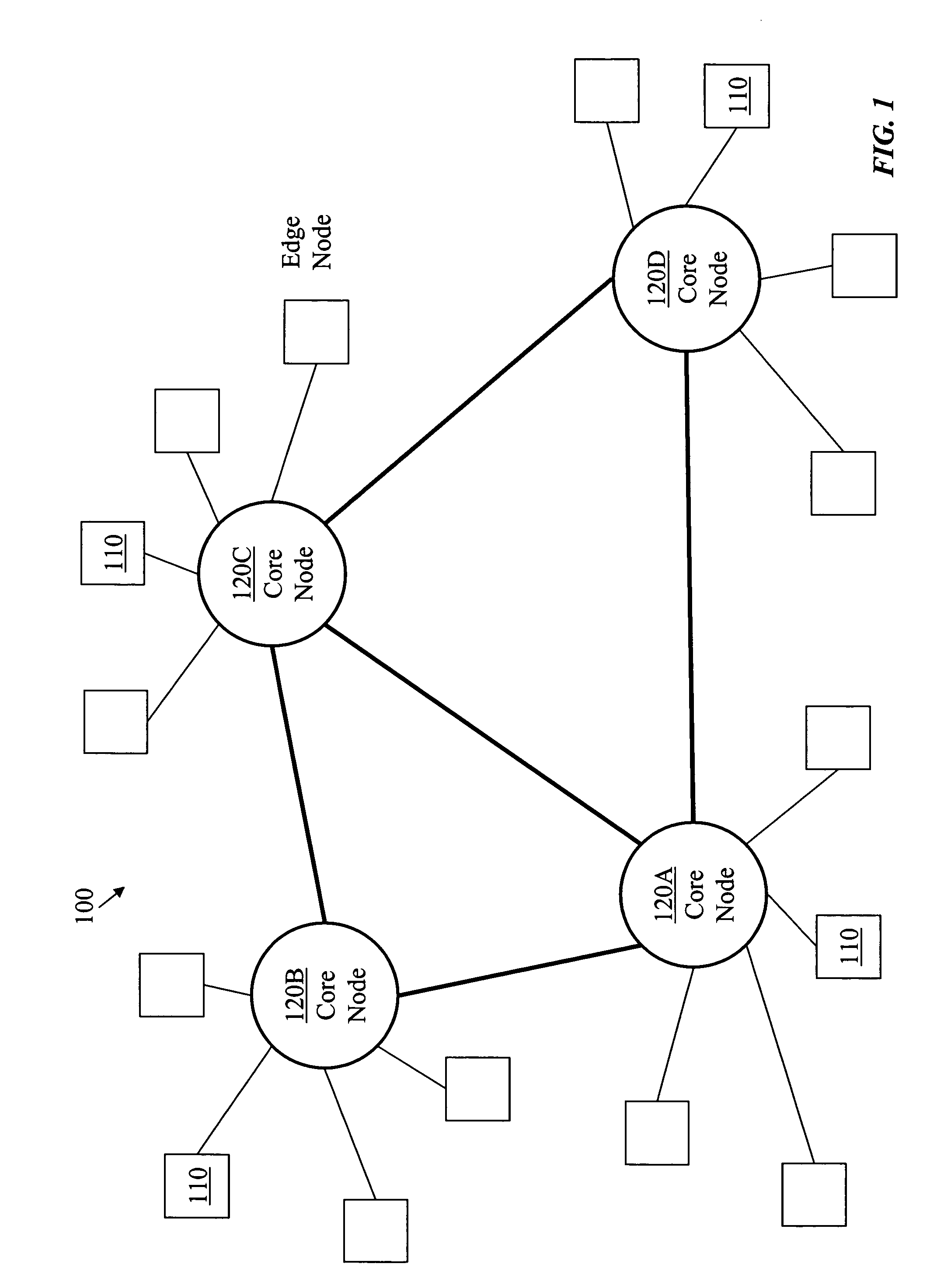
[0062]Edge node: A switching node having subtending information sources and sinks and connecting to other nodes is called an edge node.

[0063]Source node: An edge node transmitting signals, received from subtending sources, to other nodes is called a source edge node or a source node.

[0064]Sink node: An edge node receiving signals from other nodes, for delivery to subtending sinks, is called a sink edge node or a sink node.

[0065]Core node: A switching node connecting only to other switching nodes, which may be edge nodes or core nodes, is called a core node.

[0066]Input port: A port of a switching node receiving information signals from either a subtending information source or from an external node is called an input port.

[0067]Output port: A port of a switching node transmitting information signals to either a subtending information sink or an external node is called an output port.

[0068]Outer ...


PUM


Abstract

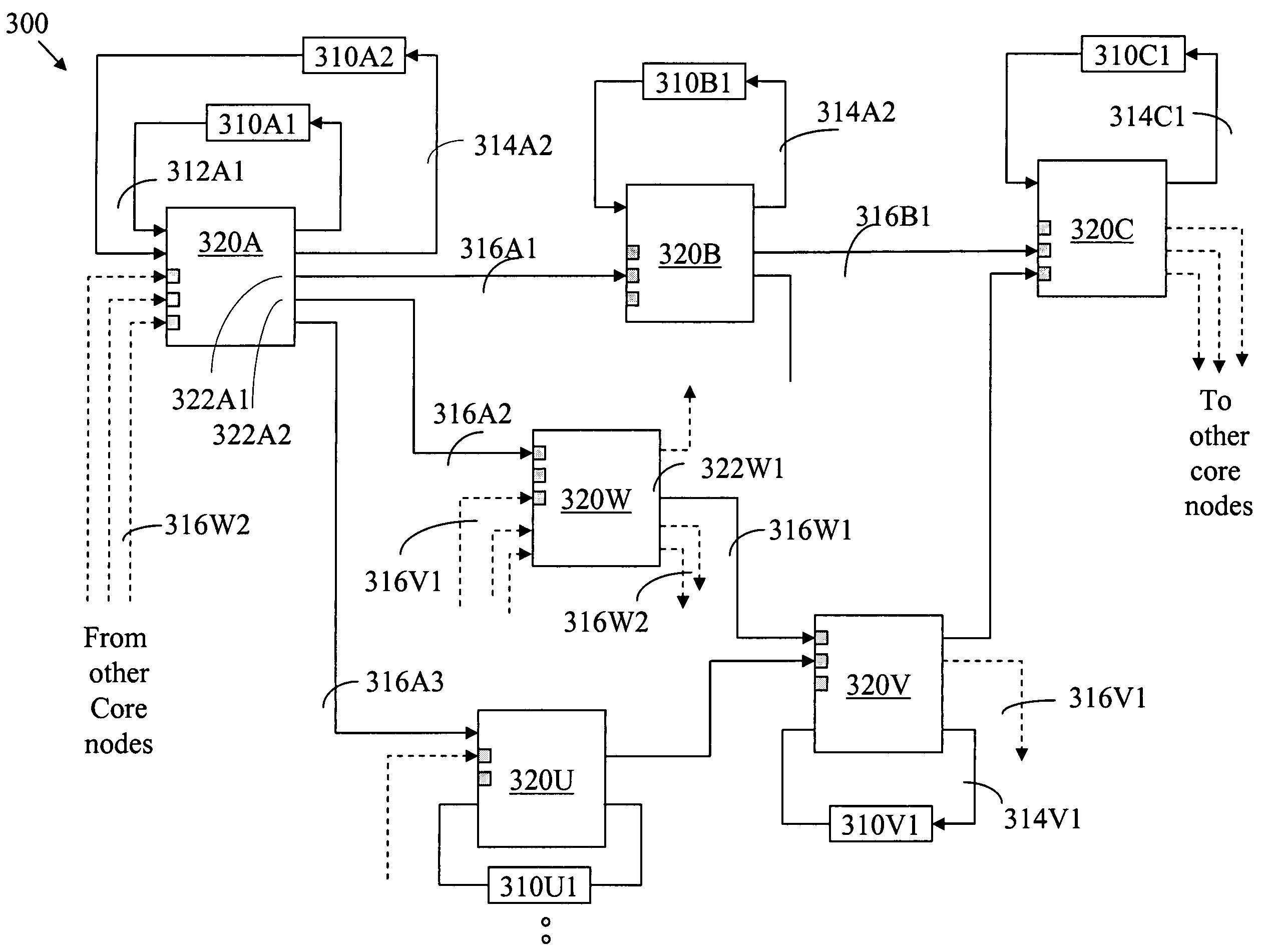
In a first mode of burst communication in a telecommunication network comprising electronic edge nodes interconnected by bufferless core nodes, data bursts are formulated at the edge nodes, respective burst descriptors are communicated to a controller of a core node, and burst-transfer schedules are sent from the core node to respective edge nodes. In a second mode, each burst-stream is allocated a flow rate and a core node determines burst sizes and schedules burst-transfer permits.
In a bimodal burst-switching network, an edge node selects to send to a core node burst-transfer requests according to the first mode, or flow-rate-allocation requests according to the second mode, depending on proximity, storage capacity at the edge node, and delay-tolerance specifications.

Description

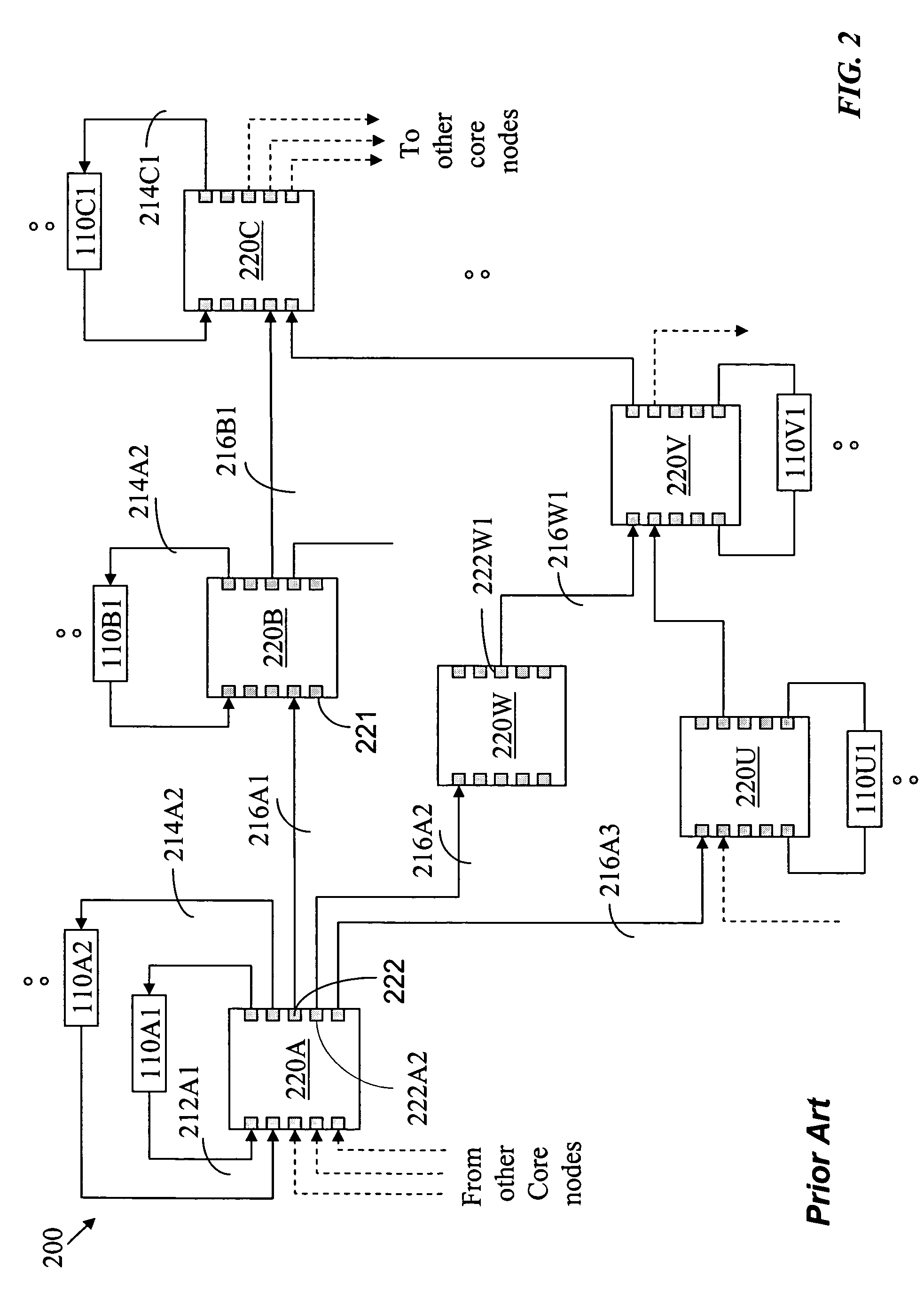
FIELD OF THE INVENTION[0001]The present invention relates to a data network having a fast-switching optical core and, in particular, to a high-performance burst-switching network having low burst-transfer delay and zero burst loss.BACKGROUND[0002]Prior-art optical burst switching has two main drawbacks: burst-transfer latency and burst loss. In a closed-loop scheme, a source node sends a request to a core node for transferring a burst, the request including a destination and size of the burst, and waits for a message from the core node, where the message acknowledges that the optical switch in the core node is properly configured, before sending the burst. In an open-loop scheme, the burst follows the burst transfer request after a predetermined time period, presumably sufficient to schedule the burst transfer across the core, and it is expected that, when the burst arrives at the core node, the controller of the core node would have set up an internal path through the optical switc...

Claims


Application Information

Patent Timeline
IPC IPC(8): H04J1/16H04J3/14
CPCH04L47/10H04L47/283H04L47/30H04Q11/0066H04L47/39H04Q2011/0064H04Q11/0071H04L47/431
Inventor BESHAL, MAGED E.JAMOUSSI, BILEL N.
Owner RPX CLEARINGHOUSE
Why Eureka
Try Eureka