Methodology for verifying multi-cycle and clock-domain-crossing logic using random flip-flop delays

a random flip-flop delay and logic verification technology, applied in the field of timing verifiers, can solve problems such as metastability and system failures, other problems can still occur with domain-crossing signals, and difficulty in confirming larger designs

Inactive Publication Date: 2007-10-30
INTELLECTUAL VENTURES I LLC
View PDF14 Cites 35 Cited by
  • Summary
  • Abstract
  • Description
  • Claims
  • Application Information

AI Technical Summary

Problems solved by technology

Verification of larger designs can be challenging.
This can pose challenges when signals from one block cross over to another block that operates at a different clock rate.
Metastability and system failures could occur if these domain-crossing signals are not properly re-synchronized.
However, other problems can still occur with domain-crossing signals.
FIG. 3 highlights a logic hazard caused by logic that combines re-synchronized clock-domain-crossing signals.
Timing hazards can occur when domain-crossing signals are combined after synchronization.
Such problems occur when the domain-crossing signals are sampled in different clock periods of the new clock.
The state machine entering state 3 may be un-expected and even un-desired.
Unfortunately, the designer may not be aware of this timing hazard, since the designer may not have designed the blocks in the CLK1 domain.
Keeping track of these many possible logic hazards is difficult and tedious.
Failures may not be observed during early simulation with idealized delays, but may appear later when better delay models using wiring-trace lengths and output loads are added.
By then it may be difficult to change the design to prevent the hazard.
Even once better R-C delay models are used for simulation, the synchronizing hazards may still appear in the future, such as when a design is moved to a new manufacturing process or when the clock frequencies used are changed.

Method used


Image

  • Methodology for verifying multi-cycle and clock-domain-crossing logic using random flip-flop delays
  • Methodology for verifying multi-cycle and clock-domain-crossing logic using random flip-flop delays
  • Methodology for verifying multi-cycle and clock-domain-crossing logic using random flip-flop delays

Examples


Embodiment Construction

[0044]The present invention relates to an improvement in logic or timing verifiers. The following description is presented to enable one of ordinary skill in the art to make and use the invention as provided in the context of a particular application and its requirements. Various modifications to the preferred embodiment will be apparent to those with skill in the art, and the general principles defined herein may be applied to other embodiments. Therefore, the present invention is not intended to be limited to the particular embodiments shown and described, but is to be accorded the widest scope consistent with the principles and novel features herein disclosed.

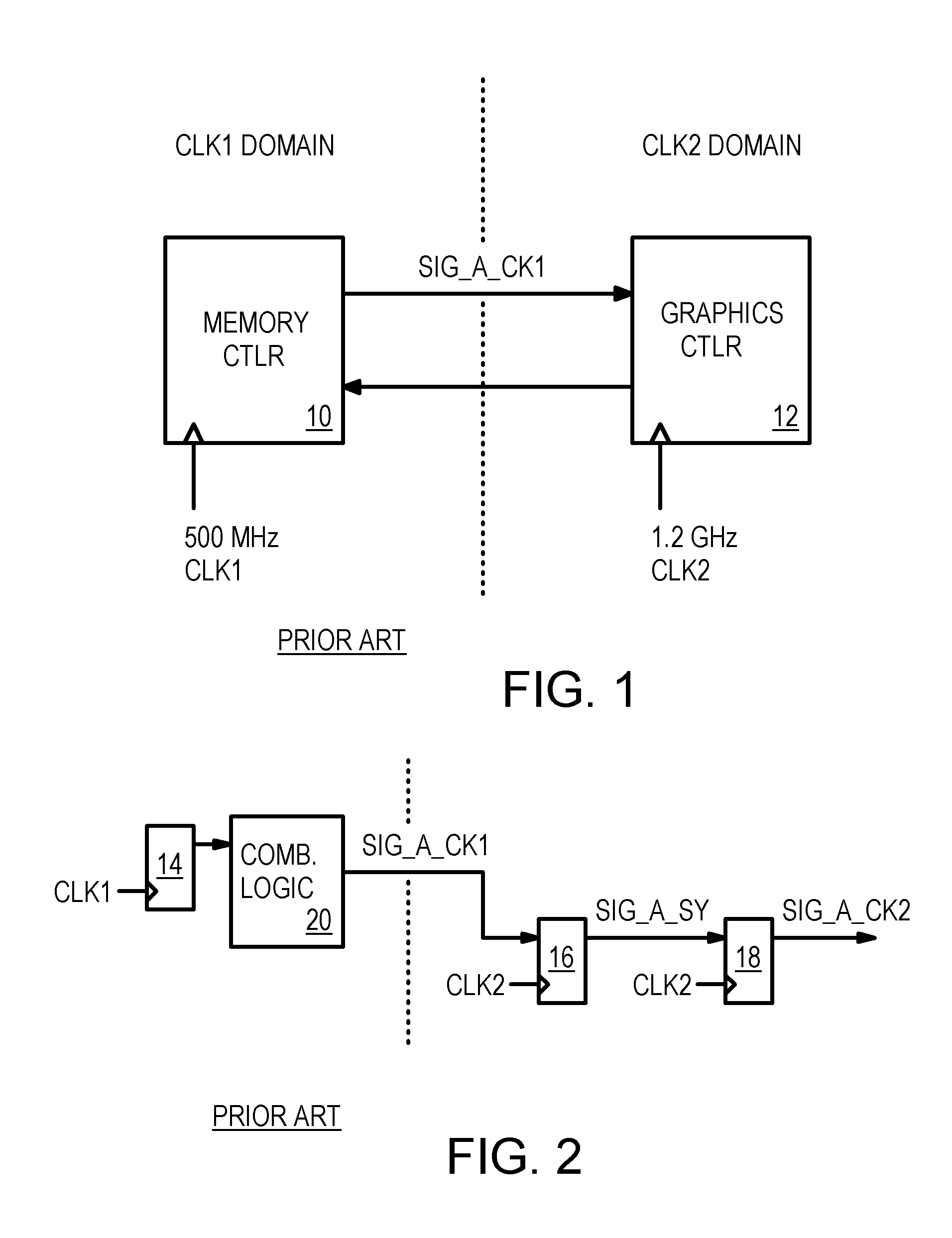
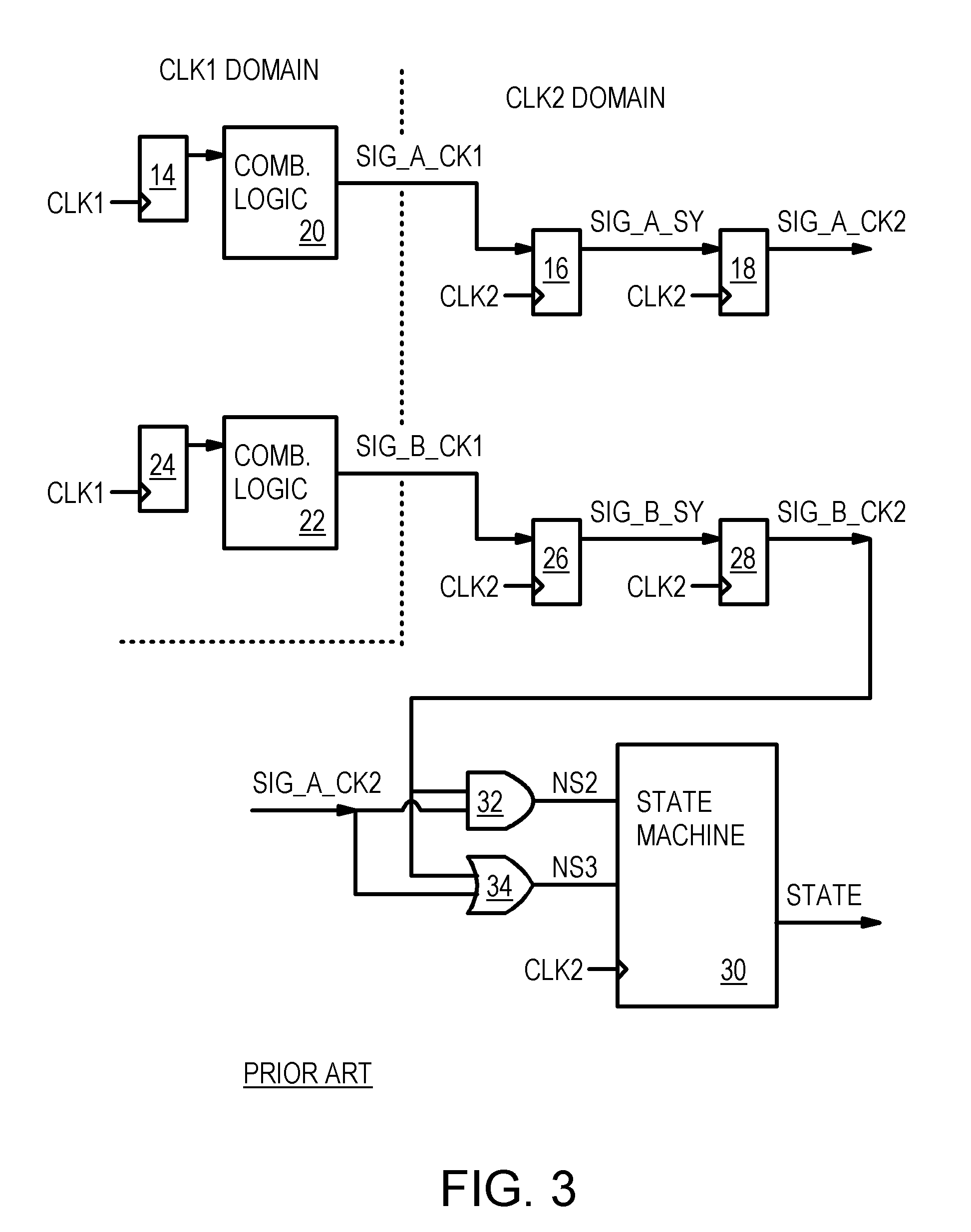
[0045]The inventor has realized that logic hazards can exist when domain-crossing signals are re-combined in the new domain. Synchronizers can prevent metastability on domain-crossing signals, but cannot prevent the combinatorial logic hazards.

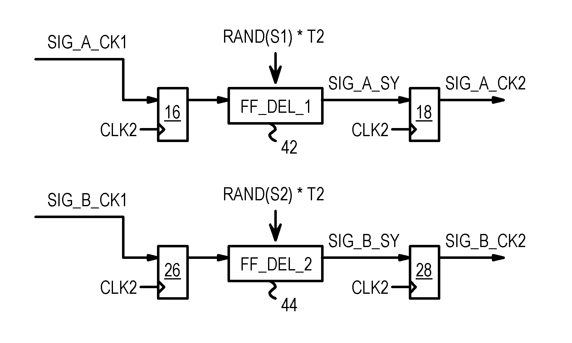
[0046]The inventor further realizes that random delays can be added to the synchro...


PUM


Abstract

A design tool inserts randomized delays into synchronizers for signals crossing from one clock domain to another. Rather than having a wide range of random delays to select from, each synchronizer's randomized delay is selected from only two possibilities. An added delay of either zero or one clock period of the new domain's clock is added as the randomized delay. The randomized delay causes the re-synchronized domain-crossing signal to become available either in the expected cycle or in the cycle following the expected cycle. Logic hazards caused by the domain-crossing signal can be detected and the possible results simulated. The synchronizer can be a series of two flip-flops, with the random delay added to the first flip-flop. Randomized delays of either one or none added periods of the clock can also be added to multi-cycle signals within one clock domain that have two or more clock cycles to propagate.

Description

BACKGROUND OF INVENTION[0001]This invention relates to design verification of digital electronic systems, and more particularly to timing verifiers.[0002]Large electronic systems can be integrated onto a single silicon substrate using advanced semiconductor manufacturing processes. A wide variety of design tools are available to help designers capture and verify these designs before committing to manufacture of prototypes. These design tools have enabled designers to build larger and larger electronic systems with about the same design effort.[0003]Verification of larger designs can be challenging. Large chips such as System-On-a-Chip (SOC) may have several major sub-system blocks, such as core logic, state machines, memories, processor cores, graphics engines, etc. Some of these large blocks may have been designed earlier by other design teams or even by other companies and can differ in details such as clock rates. This can pose challenges when signals from one block cross over to...

Claims


Application Information

Patent Timeline
Patent Type & Authority Patents(United States)
IPC IPC(8): G06F17/50G01R31/28G06F11/00
CPCG01R31/318552G01R31/318563G06F17/5031G01R31/318594G01R31/318586G06F30/3312
Inventor LEE, HIN-KWAI
Owner INTELLECTUAL VENTURES I LLC
Why Eureka
Try Eureka