
Device for measuring circularity and cylindrical shape

a technology of measuring device and cylindrical shape, which is applied in the direction of mechanical measuring arrangement, instruments, manufacturing tools, etc., can solve the problem that the inclination cannot be ignored in high-precision measuremen

Inactive Publication Date: 2007-11-06
TOKYO SEIMITSU
View PDF21 Cites 19 Cited by
  • Summary
  • Abstract
  • Description
  • Claims
  • Application Information

AI Technical Summary

Benefits of technology

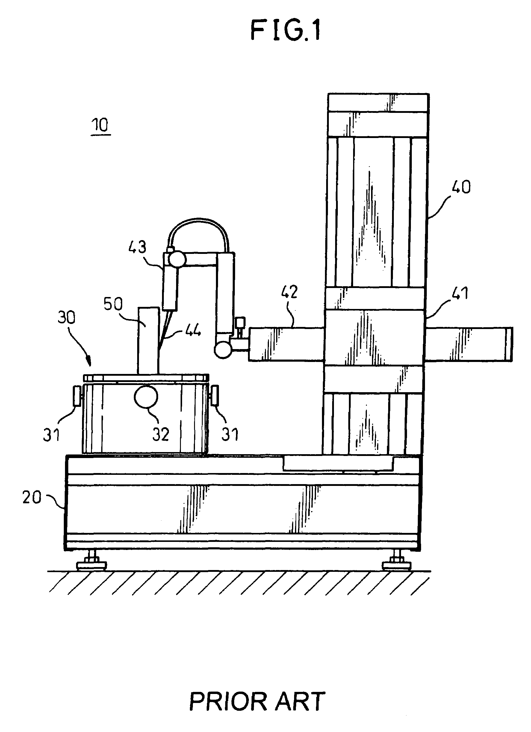
[0008]According to the conventional circularity and cylindrical shape measuring device 10, four or three legs, of which the heights can be adjusted, are provided at four corners of the base table 20 on which the rotary table 30 and the column 40 are mounted. The four or three legs are disposed at the outmost ends of the base table 20 to stabilize the device, or at Airy points (i.e., minimum deflection points) to minimize deflection of the base table 20 so that the barycenter of the device is positioned at the center of the base table 20. However, according to the circularity and cylindrical shape measuring device, there occurs a difference in sizes of deflection of the base table 20 due to variation in the weight of the workpiece 50 that is mounted on the rotary table 30. This generates an inclination in the rotation axis of the rotary table 30 and the column 40, which results in a change in the parallelism of the axis. Although this inclination is small, this inclination cannot be disregarded in high-precision measurement. When the device has a low weight, the stiffness of the column 40 and the rotary table 30 decreases, and the inclination increases.
[0009]In the light of the above conventional problems, it is an object of the present invention to provide a circularity and cylindrical shape measuring device that can decrease the measurement errors that occur due to the weight of the workpiece.
[0012]In the present invention, mass sensors that detect the mass of the workpiece are provided on the circularity and cylindrical shape measuring device. Based on detection signals from the mass sensors, the measuring device corrects an error in a measurement result generated due to deflection in the base table.

Problems solved by technology

Although this inclination is small, this inclination cannot be disregarded in high-precision measurement.

Method used


Image

  • Device for measuring circularity and cylindrical shape
  • Device for measuring circularity and cylindrical shape
  • Device for measuring circularity and cylindrical shape

Examples


first embodiment

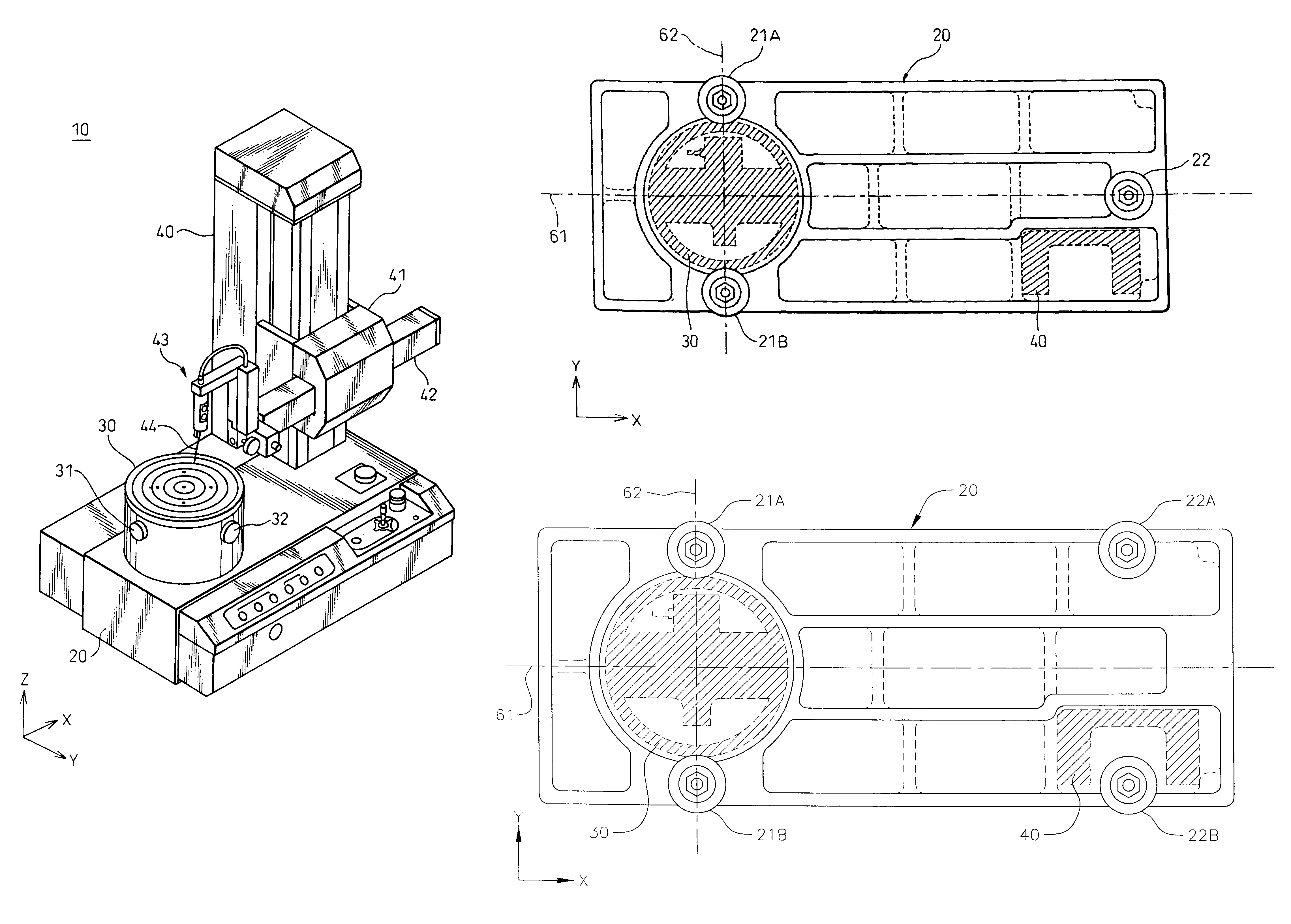
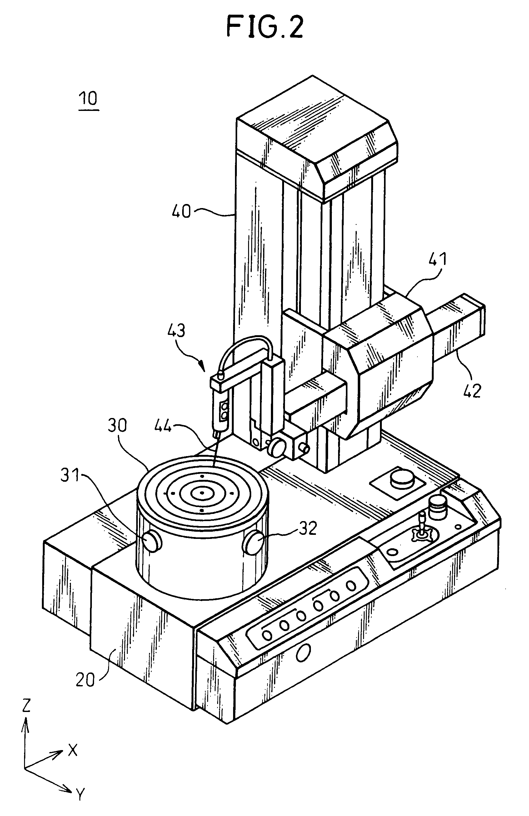
[0021]Preferred embodiments of the present invention will be described in detail below while referring to the attached figures. FIG. 2 is a perspective view showing a configuration of a circularity and cylindrical shape measuring device according to the present invention. The circularity and cylindrical shape measuring device 10 has a configuration similar to that of the device shown in FIG. 1. Functional parts of the device 10 shown in FIG. 2 identical with those shown in FIG. 1 are assigned with like reference numerals, and their explanation is omitted.

[0022]A direction of a driving axis of the column 40 is called a Z direction, and a plane perpendicular to the Z direction is called a XY plane. A direction of a straight line that connects between a rotation axis position of the rotary table 30 and a front end position of the probe 44 is called an X direction. A direction perpendicular to the X direction is called a Y direction.

[0023]FIGS. 3A and 3B are bottom plan views of the bas...

second embodiment

[0035]FIG. 6 is a perspective view showing a configuration of a circularity and cylindrical shape measuring device according to the present invention. The circularity and cylindrical shape measuring device 10 shown in FIG. 6 includes mass sensors 81 to 83 (the sensor 83 is not shown in FIG. 6) that detect the mass of the workpiece, and a measurement value correcting unit 70 such as a computer that corrects an error in a measurement result generated due to deflection of the base table 20 based on detection signals from the mass sensors 81 to 83. Functional parts of the circularity and cylindrical shape measuring device 10 shown in FIG. 6 identical with those of the device 10 shown in FIG. 1 are assigned the same reference numerals, and explanations are omitted, as with the device 10 explained with reference to FIG. 2.

[0036]The measurement value correcting unit 70 can be realized as software that operates on a controller such as a computer which controls the circularity and cylindrica...


PUM


Abstract

The invention provides a circularity and cylindrical shape measuring device that can decrease the measurement errors generated due to the weight of a measured workpiece. A circularity and cylindrical shape measuring device (10) is configured such that a rotation axis of a rotary table (30) is positioned on a leg (21) that supports a base table (20) or is positioned on a straight line that connects adjacent legs (21A and 21B)

Description

CROSS-REFERENCE TO RELATED APPLICATION[0001]This application claims priority of Japanese Patent Application Number 2004-312246, filed on Oct. 27, 2004.BACKGROUND OF THE INVENTION[0002]1. Field of the Invention[0003]The present invention relates to a device that measures circularity and cylindrical shape of a workpiece. Particularly, the invention relates to a circularity and cylindrical shape measuring device capable of preventing an error, in a measurement, resulting from deflection of a measuring table attributable to the mass of a workpiece mounted on the measuring table.[0004]2. Description of the Related Art[0005]FIG. 1 shows a configuration of a conventional device that measures circularity and cylindrical shape of a workpiece disclosed in Japanese Patent Application Unexamined Publication No. 5-231806. A rotary table 30 is rotatably provided on a base table 20 of a circularity and cylindrical shape measuring device 10. The rotary table 30 is rotated by driving a motor not sho...

Claims


Application Information

Patent Timeline
Patent Type & Authority Patents(United States)
IPC IPC(8): G01B1/00
CPCG01B5/0016G01B21/045G01B5/201
Inventor KATAMACHI, SHOZO
Owner TOKYO SEIMITSU
Learn More