Fluid product dispensing device

a technology of a dispenser device and a fluide product, which is applied in the direction of inhalators, life-saving devices, packaging, etc., can solve the problems of requiring relatively complex manipulation, requiring the use of both hands, and requiring the use of two hands for successively dispensing two half-doses into respective ones of the two nostrils, and achieving the type of energy accumulation means, which is known

Inactive Publication Date: 2007-11-06
APTAR FRANCE SAS
View PDF20 Cites 7 Cited by
  • Summary
  • Abstract
  • Description
  • Claims
  • Application Information

AI Technical Summary

Benefits of technology

[0004]An object of the present invention is to provide a fluid dispenser device, in particular of the two-dose type, that does not suffer from the above-mentioned drawbacks.

Problems solved by technology

That type of system is safe and accurate, but it requires relatively complex manipulation and therefore both hands to be used to obtain the desired result, and to make it possible to dispense the two half-doses successively into respective ones of the two nostrils.
Unfortunately, the use of two hands for dispensing the two half-doses successively into respective ones of the two nostrils may be undesirable in certain cases, and in particular, it can be necessary to have one hand free for holding the head of a child to whom the fluid is being administered, for example.
Unfortunately, such a type of energy accumulation means, which is known from the state of the art, is unreliable because the bridges of material can break while the device is in transit, i.e. before it is used.
Similarly, they do not make it possible to guarantee reliable and constant energy accumulation, it being possible for the breaking thresholds of said breakable bridges to vary due to various parameters, and in particular due to manufacturing tolerances.
In addition, it is difficult to predetermine the force required to break said bridges of material, and thus the actuating force necessary for actuating the device.

Method used


Image

  • Fluid product dispensing device
  • Fluid product dispensing device
  • Fluid product dispensing device

Examples


Embodiment Construction

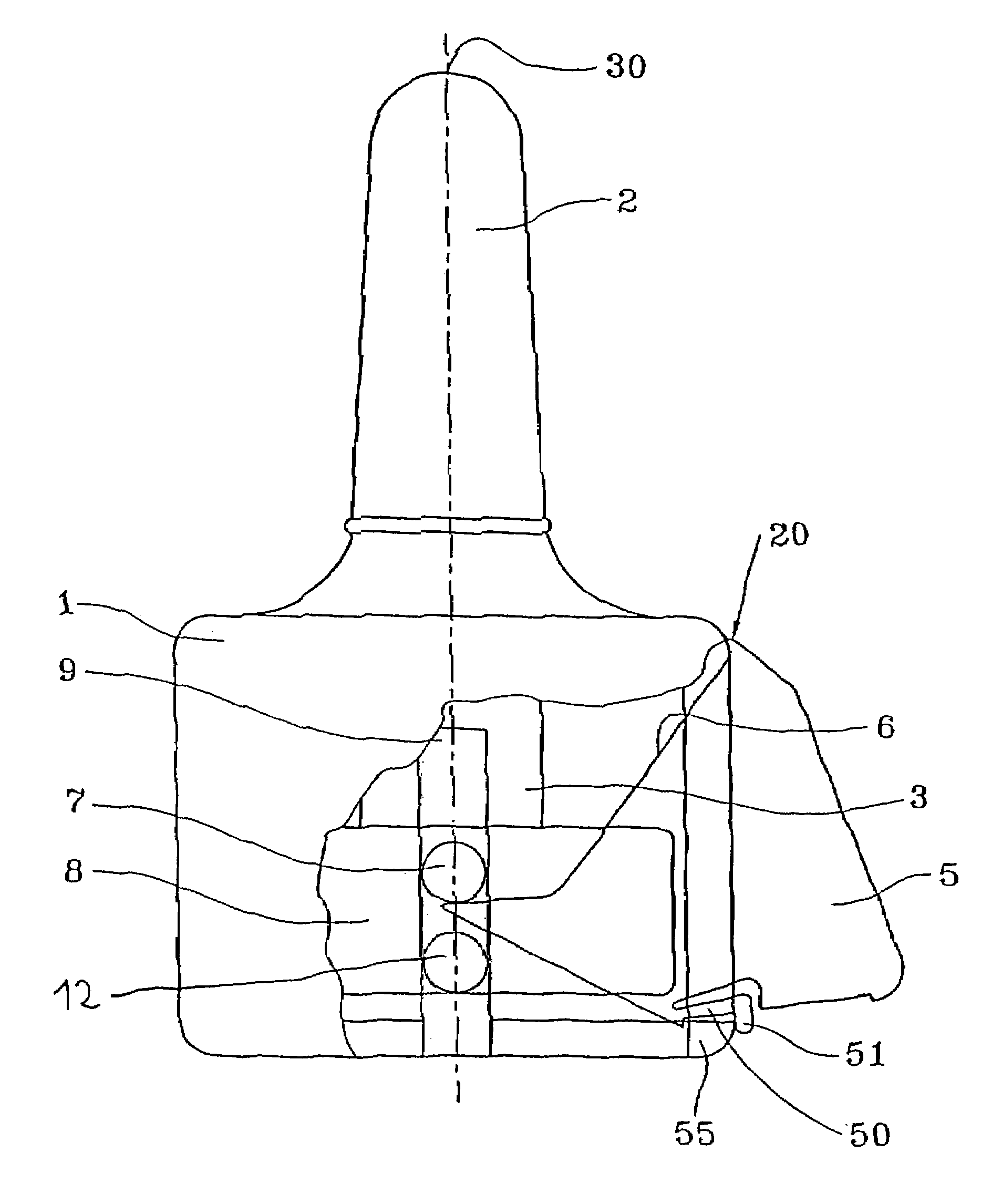
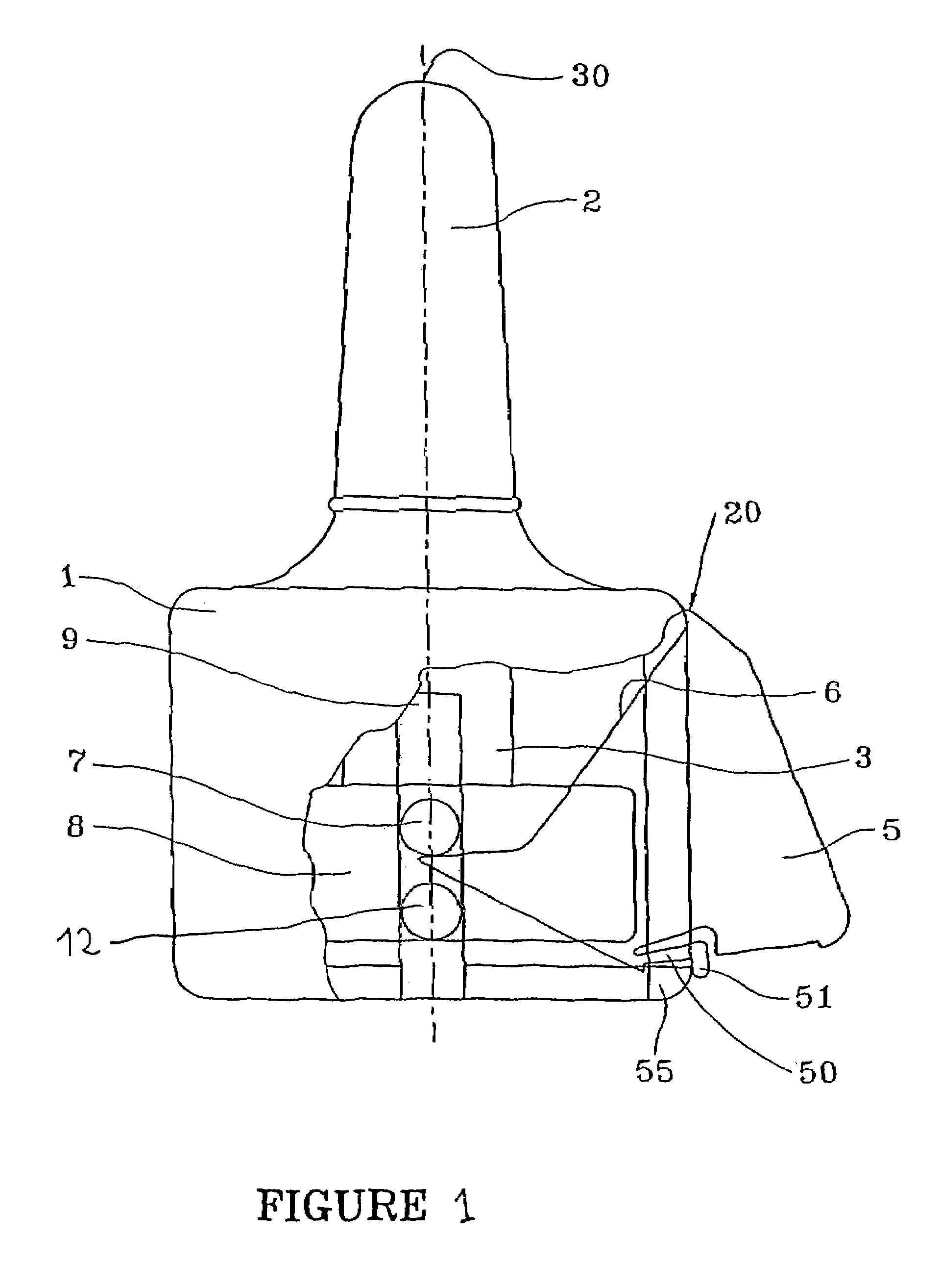
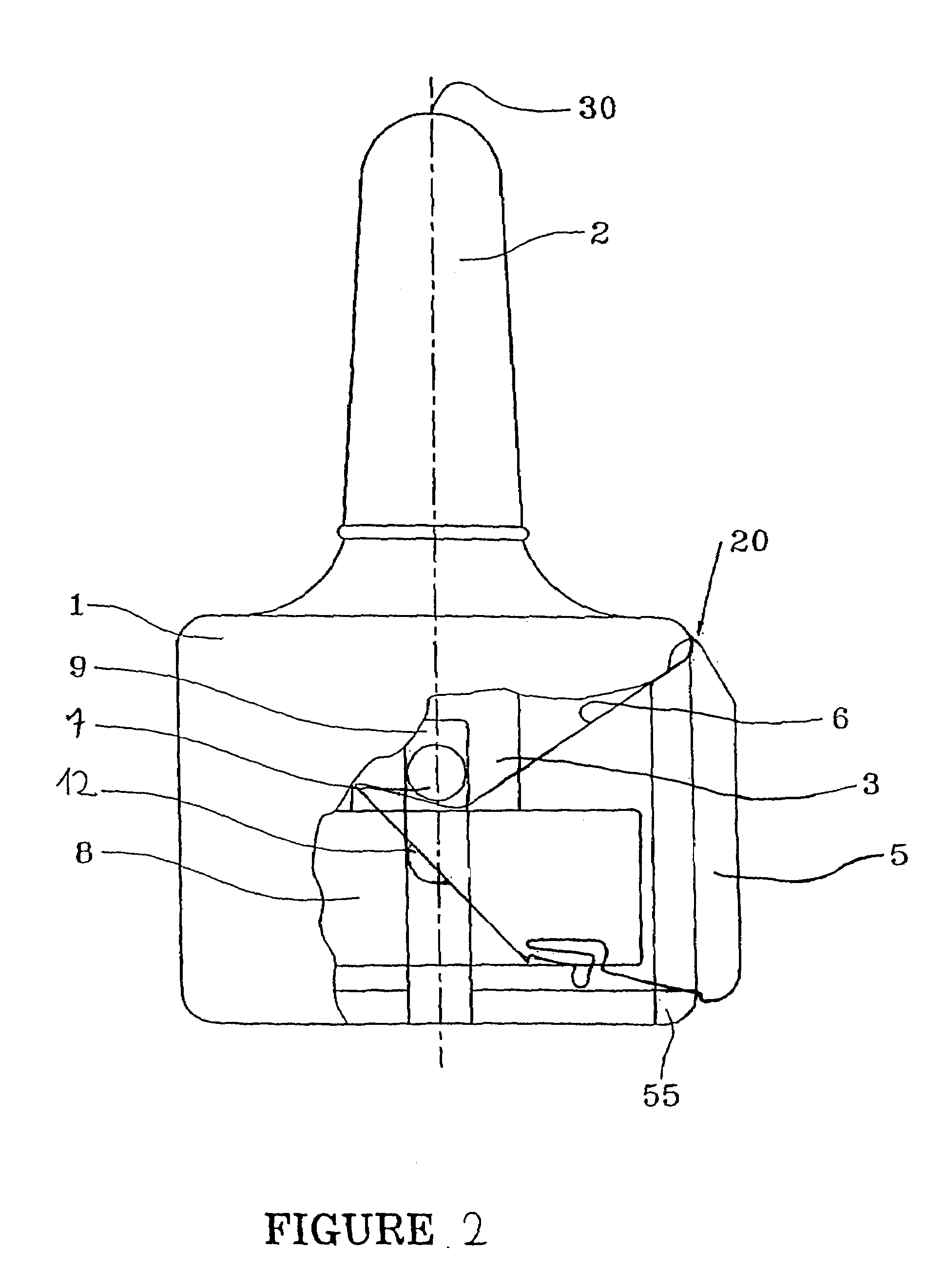
[0023]The present invention applies to any type of fluid dispenser of the two-dose type, but it is described below with reference more particularly to a device of the type disclosed in French patent application No. 00 11425, filed on Sep. 7, 2000. That patent application is therefore incorporated herein by way of reference, in particular as regards the general operation of the device, and more particularly of its actuating means and of its dose-splitting means.

[0024]French Application No. 00 114425 discloses a device that comprises a main body which supports a nasal applicator incorporating a dispensing orifice. A reservoir unit comprising a reservoir containing one dose or two half-doses of fluid is fixed into the body. The body is further provided with a hollow side sleeve which slidably receives an actuating element such as a push button. The actuating element is provided with a cam surface, which is preferably implemented in the form of one or more sloping surfaces. A dispensing...


PUM


Abstract

A fluid dispenser device having a body (1), a fluid reservoir (3) containing two half-doses, a dispensing mechanism that dispenses a half-dose of fluid upon actuation, and an energy accumulation mechanism (50, 51, 55) that accumulates energy in the hand of the user and released suddenly so that each of the half-doses is dispensed in full. The dispensing mechanism includes a dispensing member (8) mounted to slide in the reservoir (3) for dispensing the fluid, an actuating element (5) mounted to move between a rest position and an actuating position and on which the user exerts an actuating force to move the dispensing member (8) inside said reservoir (3). The actuating element is mounted to move in a direction substantially transverse to the direction in which the dispensing member (8) moves, and a dose-splitting mechanism (7, 12) dispenses a half-dose of fluid each time the dispensing mechanism is actuated.

Description

FIELD OF THE INVENTION[0001]The present invention relates to a fluid dispenser device, and more particularly to a device of the two-dose type, i.e. having two half-doses to be dispensed in succession.BACKGROUND OF THE INVENTION[0002]Dispenser devices of the two-dose type are well known. They are applicable particularly in dispensing medication and in particular vaccines into the nose. In existing devices, in order to subdivide the dose into two half-doses, e.g. so as to dispense them separately into respective ones of the two nostrils, two elements are generally provided, one supporting a reservoir, and the other supporting the piston. When they are compressed axially towards each other, the first half-dose is delivered through the dispensing orifice into the nostril. In order to subdivide the dose, the piston is stopped half way along its stroke by a shoulder, and, in order to cause it to travel over the second half of its stroke, i.e. in order to dispense the second half-dose, it ...

Claims


Application Information

Patent Timeline
Patent Type & Authority Patents(United States)
IPC IPC(8): A61M11/00A61M15/08A61J7/00B05B11/02B65D47/34B65D83/00
CPCB65D83/0005B05B11/02
Inventor STRADELLA, GIUSEPPE
Owner APTAR FRANCE SAS
Why Eureka
Try Eureka