Eureka AIR delivers breakthrough ideas for toughest innovation challenges, trusted by R&D personnel around the world.

Metal halide reactor for CVD and method

a metal halide and reactor technology, applied in chemical vapor deposition coating, inorganic chemistry, crystal growth process, etc., can solve the problems of large knudsen cells, difficult to obtain relatively pure chrome, and low efficiency of vapor deposition methods, so as to achieve low drift and reduce the effect of operation li

Inactive Publication Date: 2011-06-07
PATT TECH
View PDF14 Cites 4 Cited by
  • Summary
  • Abstract
  • Description
  • Claims
  • Application Information

AI Technical Summary

Benefits of technology

[0001]There is a need for a layer of relatively pure chrome or other metals that, while not as thick as electroplated deposits, is much thicker than the deposits used in electronic devices. These deposits would be useful for medical, frictional and corrosion proofing applications. The present deposition methods are electroplating, usually a producer of environmentally noxious residues, sputtering, a line of sight method that applies metal atoms to the surface of a target part, and various chemical vapor deposition (CVD) processes where a compound is dissociated and the metal atoms are deposited upon the part surface. The chemical vapor deposition methods can be nearly residue free but obtaining relatively pure chrome is very difficult due to the highly corrosive nature of the best (halide) precursors, the high temperatures required, the self contaminating (carbon or oxygen containing) precursors, or due to gas interactions (nitrogen). While precursor gases are obtainable in small quantities for lab scale reactors, there is a need for a precursor generation and delivery system in formation of pure chrome and other metals where a halide is the best precursor that is non-contaminating, consistent, useful in commercial scale operations, long lasting, and simple. The present invention solves and provides answers for all of the problems presently encountered with metal halide formation and delivery and has a considerable operation life with low drift.
[0003]The present invention provides a source of metal halide as a gas and the source has a life of months between the refills. Long life and copious supply is important because the need is for large scale reactors and in such reactors, refilling can add contaminants and enable leakage. There is also a need for a source of metallic compounds, especially of a metal halide, that is controllable separate from the conditions of a CVD furnace, and that is reliable and simple to use in commercial size CVD systems.

Problems solved by technology

The chemical vapor deposition methods can be nearly residue free but obtaining relatively pure chrome is very difficult due to the highly corrosive nature of the best (halide) precursors, the high temperatures required, the self contaminating (carbon or oxygen containing) precursors, or due to gas interactions (nitrogen).
An Effusion cell such as the Knudsen cell is a one use source, supplies metals, and may easily cause contamination.
Effusion cells and more specifically the Knudsen Cells are small and totally unsuited to commercial scale thick deposition systems.

Method used


Image

  • Metal halide reactor for CVD and method
  • Metal halide reactor for CVD and method
  • Metal halide reactor for CVD and method

Examples


third embodiment

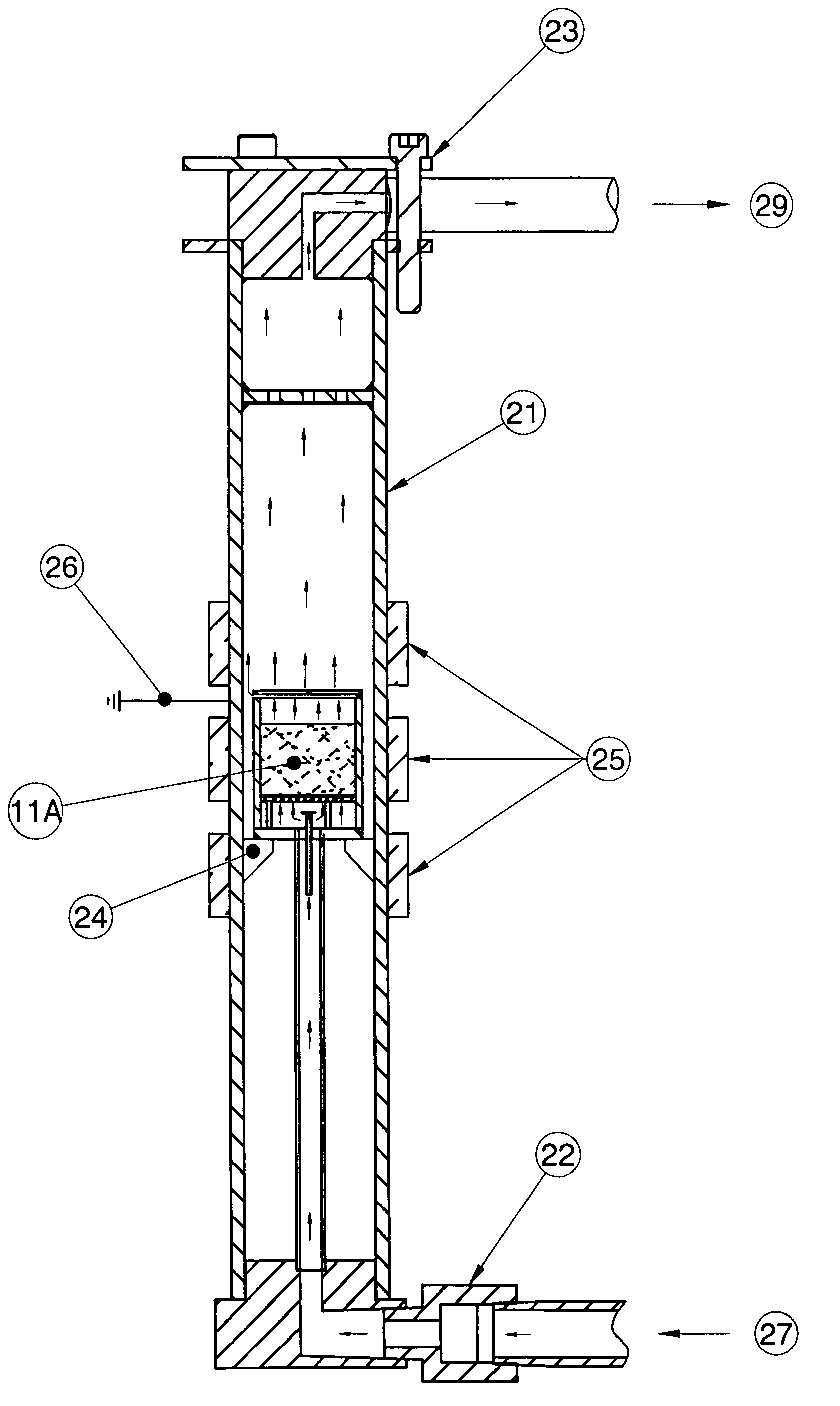
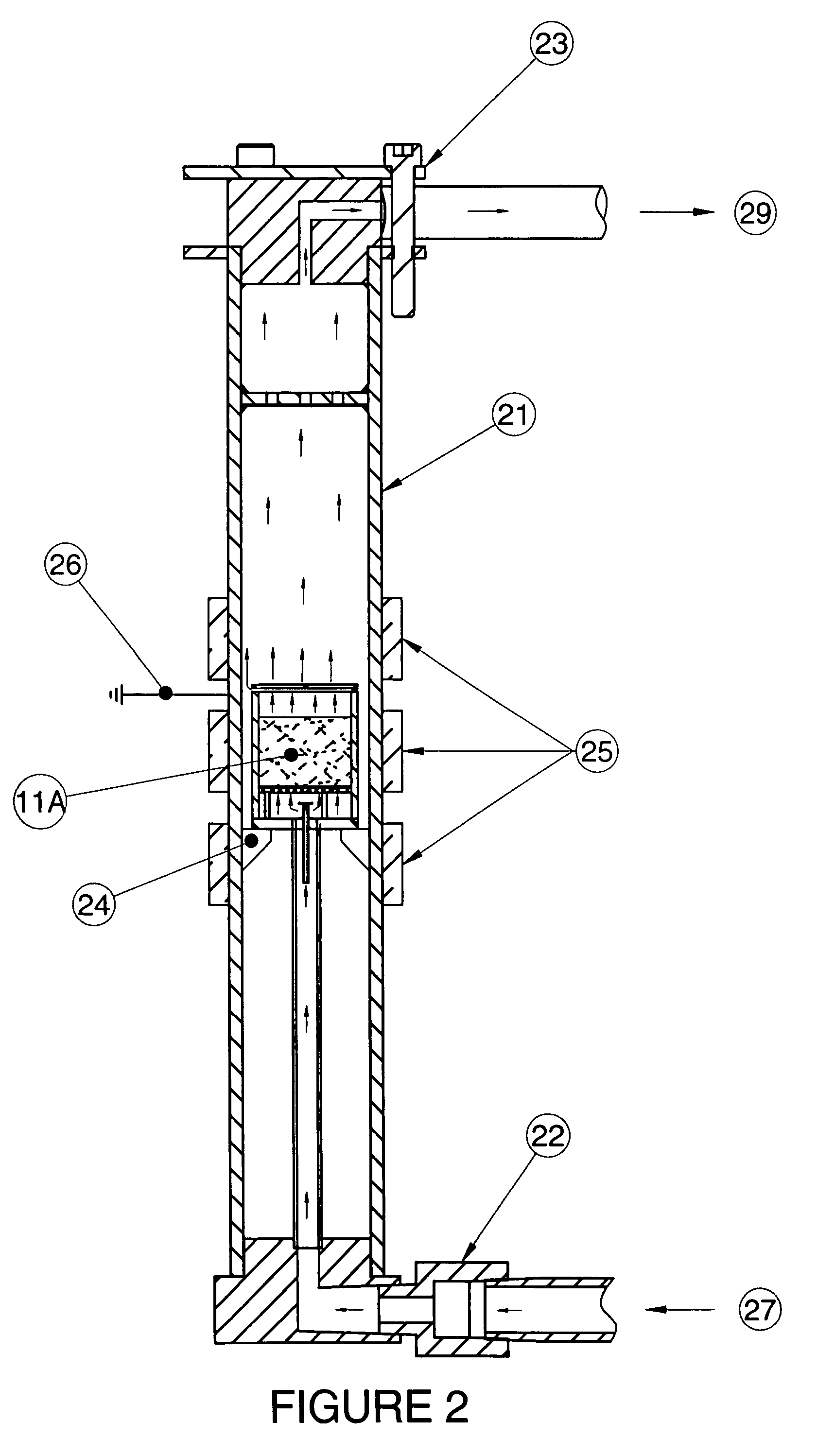
[0054]In another embodiment, the device in the third embodiment shown by FIG. 3 is further modified in FIG. 4 such that the inflow from the supply cylinder also has an added hydrogen flow 41 that is used to cool and maintain the fill in dry, reaction free state when the CVD furnace is heating or cooling or is otherwise inoperable. The inlet 2B delivers halogen gases 43 to the base of the perforated plate 44. The halogen gases go through a first layer of chromium pellets 11C and traverse upward then the partly reacted and non-reacted gases pass through a second perforated plate and into a second fill area of chromium pellets 11D prior to exit from the reaction vessel through slots 9B. This prevents channeling and insures that reactants are totally used prior to the exit slots 9B.

fourth embodiment

[0055]In a fourth embodiment a hydrogen halide gas is used as the reactant introduced into the vessel by the inlet tube.

fifth embodiment

[0056]In a fifth embodiment a halogen containing gas is used as the reactant introduced into the reactor by an inlet tube.

[0057]It is noted that the gases within the group 7 of the periodic table (any halogen) are all useful in this invention The halogen, hydrogen halide, and mixed hydrogen halides or halogens and the metals that they react with are all apparent to the skilled practitioner within this field. It is further evident that, given the concept herein the shape, specific location and the temperatures of this invention may be changed within a considerable range within these teachings.

[0058]It is further noted that any metal fill selected from a group containing the elements Cr, W, Mo, V, Zn, Mn, U, Nb. Ta, Al, Ga, Sn, Si, As, Bi, Be, and Zr are useful in this invention and that a wide variety of metal fill materials may substitute for the chromium noted as examples above. The halogen, hydrogen halide, and other halogen containing compounds as well as the metals that they rea...


PUM

PropertyMeasurementUnit
diameteraaaaaaaaaa
pressureaaaaaaaaaa
heightaaaaaaaaaa

Abstract

A reaction vessel (reactor) is shown that, filled with metal and placed either within a CVD type furnace or in a housing in fluid communication with the CVD type furnace can produce commercial quantities of a metal halide gas over extended time periods and multiple furnace runs. The control of temperature and the simplicity of this reaction vessel allows temperature differentials between the metal halide gas produced and the CVD type reactor target thus providing differing deposits. The reactor is noteworthy in that no valves, flow restrictors or other equipment which could create corrosion problems is used in the heated / reactive area of the vessel thus producing very high quality metal halide gas.

Description

SUMMARY OF INVENTION[0001]There is a need for a layer of relatively pure chrome or other metals that, while not as thick as electroplated deposits, is much thicker than the deposits used in electronic devices. These deposits would be useful for medical, frictional and corrosion proofing applications. The present deposition methods are electroplating, usually a producer of environmentally noxious residues, sputtering, a line of sight method that applies metal atoms to the surface of a target part, and various chemical vapor deposition (CVD) processes where a compound is dissociated and the metal atoms are deposited upon the part surface. The chemical vapor deposition methods can be nearly residue free but obtaining relatively pure chrome is very difficult due to the highly corrosive nature of the best (halide) precursors, the high temperatures required, the self contaminating (carbon or oxygen containing) precursors, or due to gas interactions (nitrogen). While precursor gases are ob...

Claims


Application Information

Patent Timeline
Patent Type & Authority Patents(United States)
IPC IPC(8): B01J8/02C01B9/00
CPCC30B25/14C23C16/4488
Inventor PATROVSKY, HUBERT
Owner PATT TECH
Why Eureka
Eureka Blog
Learn More