High efficiency, high slew rate switching regulator/amplifier

a switching regulator and high-efficiency technology, applied in the direction of power conversion systems, dc-dc conversion, instruments, etc., can solve the problems of large ripple current and conduction loss values, large switching losses, and lower efficiency, and achieve high slew rate capability, rapid reduction of load current, and increased slew rate capability

Inactive Publication Date: 2007-11-06
COLLABO INNOVATIONS INC
View PDF47 Cites 25 Cited by
  • Summary
  • Abstract
  • Description
  • Claims
  • Application Information

AI Technical Summary

Benefits of technology

[0013]The switching regulator / amplifier of the present invention provides numerous advantages over the prior art. One advantage of the present invention is that it provides a highly efficient switching regulator / amplifier that minimizes the power requirements for operation. This is accomplished in-part by reducing the power dissipated by the linear amplifier contained in the device, by providing a separate current path that is capable of providing the steady state current requirements to the load (i.e., the linear amplifier is activated only during fast changing transient voltage swings in the load). As a result, as one example, the present invention advantageously allows for an extension of battery operation time of a cell phone between charges.
[0014]In addition, the switching regulator / amplifier provides for an increased slew rate capability. As the result of the design of the present invention, which incorporates the use of a “free-wheeling” switch, it is possible to rapidly reduce the load current to substantially zero (i.e., on the order of a few nanoseconds). Moreover, when the load current is reduced in the foregoing manner, the design of the present invention does not immediately dissipate the current (i.e., as explained below the current is temporarily stored), and therefore if the load must be increased shortly after the reduction, the stored current is again coupled / provided to the load. The foregoing operation allows the switching regulator / amplifier of the present invention to exhibit both a high slew rate capability and increased operating efficiency.
[0015]Yet another advantage of the present invention is that the design provides a “feed-forward” control system in which the switching regulator / amplifier reacts to changes in the desired voltage set point when adjusting the current delivered to the load. The control of the switching regulator / amplifier does not utilize the output voltage signal. As a result, the design of the present invention further improves both slew rate performance (as the load current is adjusted more rapidly in comparison to a device that modifies the current delivered to the load based on changes in the output voltage of the regulator) and efficiency performance (as there is no sense resistor coupled to the output of device, which would result in an increase in power dissipation).

Problems solved by technology

However, the use of such low value inductors results in large values of ripple current and conduction losses, while high switching frequencies result in larger switching losses, both of which undesirably lower efficiency.

Method used


Image

  • High efficiency, high slew rate switching regulator/amplifier
  • High efficiency, high slew rate switching regulator/amplifier
  • High efficiency, high slew rate switching regulator/amplifier

Examples


Embodiment Construction

[0025]The present invention now will be described more fully hereinafter with reference to the accompanying drawings, in which preferred embodiments of the invention are shown. This invention may, however, be embodied in many different forms and should not be construed as limited to the embodiments set forth herein: rather, these embodiments are provided so that this disclosure will be thorough and complete, and will fully convey the scope of the invention to those skilled in the art, like numbers refer to like elements throughout.

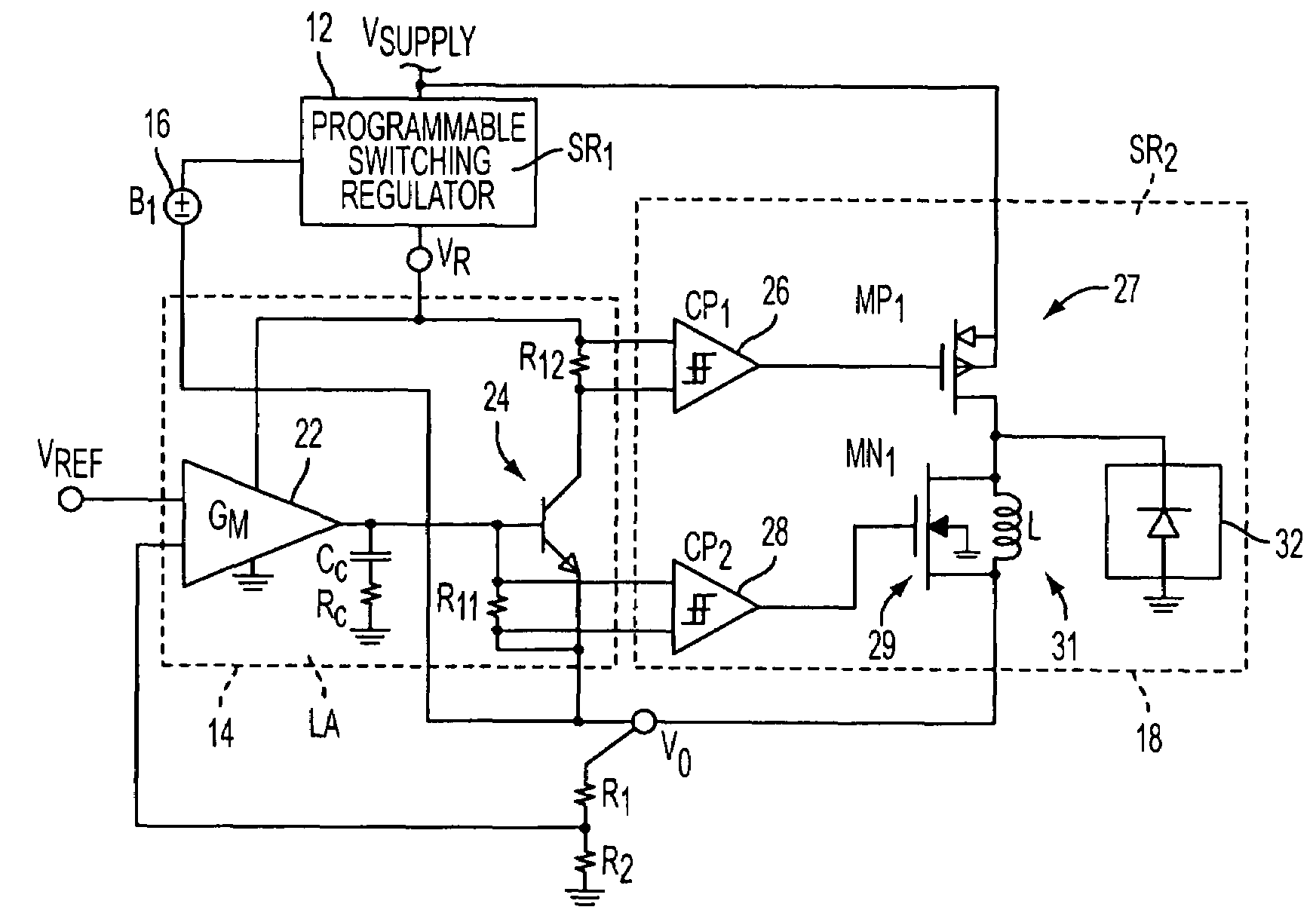
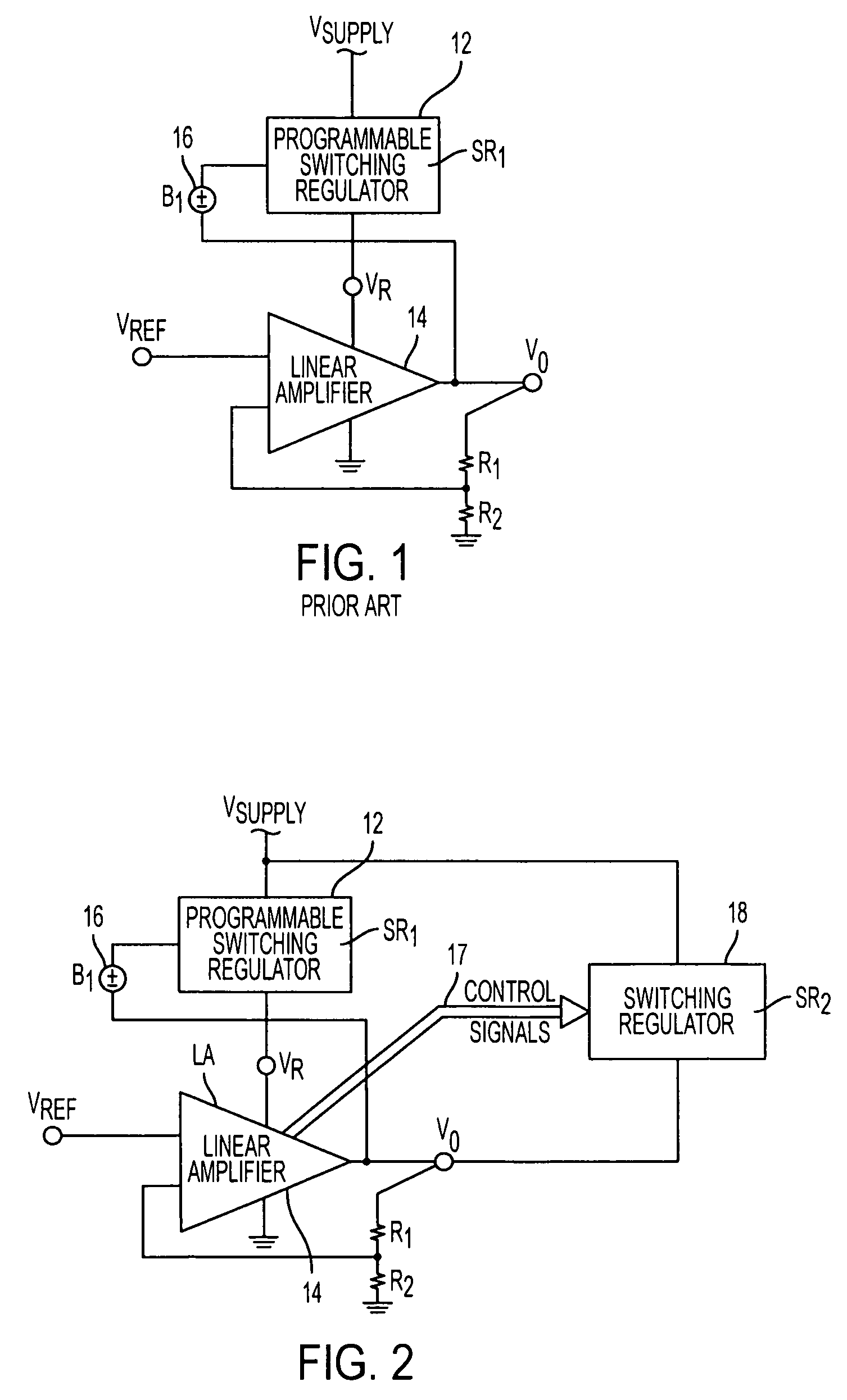
[0026]Referring to FIG. 2, similar to the prior art design illustrated in FIG. 1, the switch regulator / amplifier of the present invention comprises a programmable switching regulator 12 cascaded with a linear amplifier stage 14, as well an overhead voltage supply 16 and resistors R1 and R2. The linear amplifier stage 14 receives VREF as an input signal. The foregoing components are coupled together in the same manner as illustrated in FIG. 1. However, the ...


PUM


Abstract

A regulating apparatus having an output node and being operative for regulating the voltage level at the output node in response to a reference signal provided as an input to the regulating apparatus. The regulating apparatus includes a linear amplifier stage operative for receiving the reference signal and being capable of sourcing current to the output node when the reference signal indicates that a present voltage level at the output node is less than a desired voltage level at the output node. The regulating apparatus also includes a switching regulator, which is controlled by the linear amplifier stage, and which is operative for sourcing current to the output node when the amount of current being sourced to the output node by the linear amplifier stage exceeds a predetermined threshold.

Description

CLAIM OF PRIORITY[0001]This patent application, and any patent(s) issuing therefrom, claims priority to U.S. provisional patent application No. 60 / 628,652, filed on Nov. 18, 2004, which is incorporated herein by reference in its entirety.FIELD OF THE INVENTION[0002]The present invention relates to an improved switching regulator and / or amplifier, and more specifically, to a novel, cost effective design for a switching regulator and / or amplifier that provides for both high efficiency and high slew rate.BACKGROUND OF INVENTION[0003]It has been known in the prior art to utilize switching regulators / amplifiers in applications such as, but not limited to: (1) voltage regulators utilized for supplying a relatively fixed DC voltage to a load whose current demands change very quickly such as CMOS logic processors whose activity can go from negligible (such as in standby) to very high or vise-versa in a few nanoseconds, for example, at the change of state of a control signal; and (2) “digita...

Claims


Application Information

Patent Timeline
Patent Type & Authority Patents(United States)
IPC IPC(8): G05F1/59
CPCH02M3/1584H02M2001/0045H02M1/0045
Inventor OSWALD, RICHARDYAMAMOTO, TAMOTSUISHI, TAKUYA
Owner COLLABO INNOVATIONS INC
Why Eureka
Try Eureka